
Conduit Bending: Offset, Saddle, and Stub-Up Multipliers
- 04 Aug, 2026
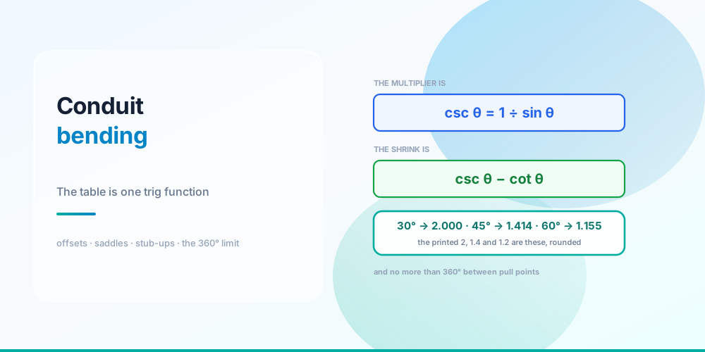
Every apprentice memorises the same five numbers: 10° is 6, 22.5° is 2.6, 30° is 2, 45° is 1.4, 60° is 1.2.
They’re cosecants. The offset multiplier is 1 ÷ sin θ, and the printed table is that function evaluated at five angles and rounded. Once you know that, you don’t need the table - and more usefully, you can work at any angle your bender will make, not just the five that got printed.
The shrink table is one function too: csc θ − cot θ.
The Multiplier Is a Cosecant
The multiplier table is one trig function, rounded
| Bend angle | Exact csc θ | Printed | Rounding error |
|---|---|---|---|
| 10° | 5.759 | 6 | +4.2% |
| 22.5° | 2.613 | 2.6 | −0.5% |
| 30° | 2.000 | 2 | 0.0% |
| 45° | 1.414 | 1.4 | −1.0% |
| 60° | 1.155 | 1.2 | +3.9% |
The geometry is straightforward once you see it. An offset is a right triangle: the offset height is the opposite side, and the length of conduit between the two bend marks is the hypotenuse. Hypotenuse = opposite ÷ sin θ. That’s it.
30° is exactly 2.000, which is why it’s the angle everyone defaults to - the arithmetic is a doubling you can do on a ladder.
10° and 60° carry the real rounding error, around 4% each. On a 2-inch offset that’s nothing. On a 12-inch offset at 10°, using 6 instead of 5.759 puts your second mark nearly 3 inches long, and on a shallow offset in a tight space that’s the difference between a clean job and a re-bend. Use 5.76.
Shrink Is Also One Function
The second table is shrink per inch of offset, and it’s what people forget entirely - then find their run is short at the far end.
| Bend angle | Exact csc θ − cot θ | Printed |
|---|---|---|
| 10° | 0.087 in | 1∕16 in |
| 22.5° | 0.199 in | 3∕16 in |
| 30° | 0.268 in | 1∕4 in |
| 45° | 0.414 in | 3∕8 in |
| 60° | 0.577 in | 1∕2 in |
Where does it come from? Without the offset, covering that horizontal distance would take height ÷ tan θ of conduit. With the offset you use height ÷ sin θ. The difference - csc θ − cot θ per inch of offset - is length the offset consumed.
Note the last two rows. The printed table says 3∕8 in at 45° where the true figure is 0.414 (nearly 7∕16), and 1∕2 in at 60° where the true figure is 0.577 (nearly 9∕16). The published shrink table is optimistic at the steep angles, so a deep 45° or 60° offset comes out slightly short if you trust it. It’s accurate at 22.5° and 30°, which is another argument for staying shallow.
The Same Offset, Five Ways
The same 6 in offset, five ways
| Angle | Marks apart | Shrink |
|---|---|---|
| 10° | 34.55 in | 0.52 in |
| 22.5° | 15.68 in | 1.19 in |
| 30° | 12.00 in | 1.61 in |
| 45° | 8.49 in | 2.49 in |
| 60° | 6.93 in | 3.46 in |
That’s the whole trade-off in one table. A shallow offset needs a long run of straight conduit to develop in but barely shortens the pipe; a steep one is compact and eats over half an inch of length per inch of offset.
Which to pick:
- 10° or 22.5° for shallow offsets where you have room - easier pulls, minimal shrink, and much less chance of kinking.
- 30° as the default. The multiplier is 2, the shrink is a clean quarter inch, and it develops in a sensible length.
- 45° where space is tight. Watch the shrink and use 0.414 rather than 3∕8.
- 60° only where you must. Steep offsets are hard on the conductors during the pull as well as on the pipe.
And the pull matters: shallower bends pull easier. Two 30° bends put far less sidewall pressure on the conductors than two 60° bends covering the same offset.
Stub-Ups and Take-Up
A 90° stub is the one bend that doesn’t use a multiplier. Instead you subtract the bender’s take-up from the desired stub height and put the arrow there.
| Conduit | Typical take-up |
|---|---|
| ½ in EMT | 5 in |
| ¾ in EMT | 6 in |
| 1 in EMT | 8 in |
| 1¼ in EMT | 11 in |
Take-up is a property of the bender, not the conduit - it’s stamped on the tool, and it varies between manufacturers and between hand benders and mechanical ones. Read the bender you’re holding rather than the table above. A 12-inch stub in ½ in EMT with a 5-inch take-up gets its mark at 7 inches.
Saddles
Three-bend saddle - for crossing a pipe or a small obstruction. A 45° centre bend with two 22.5° outer bends:
- Mark the centre of the obstruction on the conduit; that’s the centre bend.
- The outer marks go 2.5 × the obstruction height each side of the centre mark.
- Shrink is 3∕16 in per inch of obstruction height.
For a 2-inch obstruction: outer marks 5 inches each side, shrink 0.375 in. The centre notch on a hand bender is what you line the centre mark up with; the arrow is used for the outer bends.
Four-bend saddle - two offsets back to back, for a wide obstruction such as a duct or a beam. Compute it as two independent offsets. It’s more forgiving to lay out than a three-bend saddle and costs more degrees.
The Constraint Nobody Mentions: 360°
Four bends, and what each spends of your 360°
NEC 358.26 (EMT), 344.26 (RMC) and 352.26 (PVC) all say the same thing: not more than the equivalent of four quarter bends - 360° total - between pull points.
That’s a budget, and bends spend it:
| Bend | Degrees |
|---|---|
| Stub-up (90°) | 90 |
| Offset at 30° | 60 |
| Three-bend saddle | 90 |
| Four-bend saddle | 120 |
Four 90s spends the entire budget with nothing left for an offset. So a run that goes up a wall, across a ceiling, along a beam and down again is already at the limit before you’ve dodged a single duct - and the answer is a pull box or a condulet, decided at layout time rather than discovered when the pull won’t go.
This is why the 360° rule is really a design rule, not a bending rule. Two related points:
Shallow offsets are cheaper in degrees too. Two 10° bends cost 20°; two 45° bends cost 90°. If you’re near the budget, going shallow buys you room in both senses.
The rule is about pulling tension, not about the pipe. Every degree of bend multiplies the sidewall pressure on the conductors, and past 360° the pull force rises fast enough to damage insulation. That’s also why it’s measured between pull points rather than per fitting.
Bend Radius and Damage
Two more code requirements that constrain how you bend:
Minimum bend radius - Chapter 9, Table 2 gives the minimum radius for field bends by conduit size and by whether a one-shot or full-shoe bender is used. A hand bender’s shoe already satisfies it; the constraint bites on large sizes and on hydraulic benders.
No damage and no reduction of internal diameter - 358.24 for EMT and its equivalents. In practice: a kink or a flattened bend fails, both because it reduces the internal diameter and because it will cut insulation during the pull. A wrinkled outside radius is usually cosmetic; a flat spot on the inside is not.
Note also that conduit fill assumes the internal area of the pipe, so a deformed bend quietly invalidates the fill calculation as well. Fill is covered in How to Calculate Conduit Fill and the Conduit Fill Chart.
Common Mistakes
- Memorising the multipliers instead of csc θ. The function works at every angle; the table works at five.
- Using 6 for 10°. The true value is 5.759 - a 4% error that shows up on deep shallow offsets.
- Trusting 3∕8 in of shrink at 45°. It’s 0.414. The printed table is low at 45° and 60°.
- Forgetting shrink entirely. Every offset shortens the run. Add it back before you cut.
- Using the table’s take-up instead of the bender’s. Take-up is stamped on the tool and varies.
- Bending the outer saddle marks from the obstruction instead of the centre mark. 2.5 × height each side of the centre.
- Ignoring the 360° budget. Four 90s and you’re done; plan pull boxes at layout.
- Choosing 60° for convenience. Steep bends cost degrees, shrink and pulling tension all at once.
- Accepting a kinked bend. It reduces the internal diameter, breaks 358.24, and will damage insulation on the pull.
Size the Raceway First
Conduit Fill Calculator - pick the conduit type, trade size and conductors and it applies the Chapter 9 Table 1 fill limits, so you know what you’re bending before you bend it.
Bending is the last step; the raceway size and the conductors come first. See How to Calculate Conduit Fill for the method, the Conduit Fill Chart for the lookup, and Wire Derating Explained for the constraint that usually binds before fill does. The NEC Tables reference has the Chapter 9 data.
Sources & standards: NEC (NFPA 70) 2023 - 344.24, 344.26, 352.24, 352.26, 358.24, 358.26, and Chapter 9 Table 2 for minimum field-bend radii. Multiplier and shrink values are computed from the geometry (csc θ and csc θ − cot θ); the printed values on benders are rounded. Take-up figures are typical hand-bender values and vary by manufacturer - read the tool. Have electrical work installed by a licensed electrician under permit.
FAQ
What are the conduit offset multipliers?
10° is 6, 22.5° is 2.6, 30° is 2, 45° is 1.4 and 60° is 1.2 - and they’re all cosecants of the bend angle, rounded. The exact values are 5.759, 2.613, 2.000, 1.414 and 1.155. Multiply the offset height by the multiplier to get the distance between your two bend marks.
Why is the 30 degree multiplier exactly 2?
Because the sine of 30° is exactly 0.5, so its cosecant is exactly 2.000. That’s the only one of the five common angles with a clean value, which is why 30° is the default offset angle in the trade - the arithmetic is a doubling you can do without a calculator.
How do I calculate conduit shrink?
Shrink per inch of offset is csc θ − cot θ: 0.087 in at 10°, 0.199 at 22.5°, 0.268 at 30°, 0.414 at 45° and 0.577 at 60°. Multiply by the offset height. Note that the commonly printed table gives 3∕8 in at 45° and 1∕2 in at 60°, both of which understate the true figure - so a deep steep offset comes out short if you trust it.
What is take-up on a conduit bender?
The distance from the end of the conduit to the point where the bend begins, which you subtract from the desired stub height to place your mark. It’s typically 5 in for ½ in EMT, 6 in for ¾ in, 8 in for 1 in and 11 in for 1¼ in - but it’s a property of the bender rather than the conduit, it’s stamped on the tool, and it varies between manufacturers.
How do I bend a three-bend saddle?
Mark the centre of the obstruction on the conduit and make a 45° bend there using the bender’s centre notch. Then mark 2.5 times the obstruction height on each side of that centre mark and make a 22.5° bend at each, in the opposite direction. Shrink is 3∕16 inch per inch of obstruction height. For a 2-inch obstruction the outer marks are 5 inches out and the shrink is 0.375 inch.
How many bends are allowed in a conduit run?
Not more than the equivalent of four quarter bends - 360° total - between pull points, per 358.26 for EMT and the equivalent sections for RMC and PVC. Budget it: a 90° stub costs 90°, a 30° offset costs 60°, a three-bend saddle 90° and a four-bend saddle 120°. Four 90s spends the whole allowance with nothing left over.
Why does the 360 degree limit exist?
Because every degree of bend increases the sidewall pressure the conductors experience during the pull, and past about 360° the required pulling force rises steeply enough to risk damaging insulation. It’s a pulling limit, not a structural one, which is why it’s measured between pull points rather than per fitting - and why adding a pull box is the fix rather than reducing bend radius.
Which offset angle should I use?
30° for most work: the multiplier is exactly 2, shrink is a clean quarter inch, and it develops in a sensible length. Go shallower to 22.5° or 10° where you have the room, because the pull is easier, the shrink is smaller and it costs fewer degrees against the 360° budget. Save 45° and 60° for tight spaces, and use the exact shrink figures when you do.