
Transformer Sizing: kVA, Primary and Secondary OCPD (NEC 450.3)
- 04 Aug, 2026
Two things about transformer protection surprise people who are otherwise comfortable with the NEC.
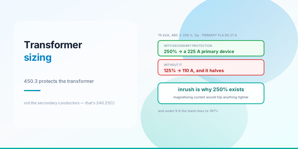
The primary overcurrent device may be set at 250% of full-load current - double what any ordinary feeder would permit - but only where the secondary is separately protected. Take that protection away and you drop to 125%.
And NEC 450.3 does not protect the secondary conductors. It protects the transformer. The conductors leaving the secondary are governed by 240.21(C), a completely different section, and forgetting it is the most common transformer violation there is.
The Calculation
60 kVA of load, 25% growth, 480 → 208 V three-phase
Sizing the transformer itself is straightforward: take the calculated load, add growth, and round up to a standard kVA rating. 60 kVA plus 25% is 75 kVA, which is a standard rating exactly.
Then the currents, from the three-phase formula:
FLA = kVA × 1000 ÷ (V × √3)- Primary at 480 V: 75,000 ÷ (480 × 1.732) = 90.21 A
- Secondary at 208 V: 75,000 ÷ (208 × 1.732) = 208.18 A
Then the devices:
| Side | Rule | Calculation | Device |
|---|---|---|---|
| Primary | 450.3(B), with secondary protection | 90.21 × 250% = 225.5 A | 225 A |
| Secondary | 450.3(B) | 208.18 × 125% = 260.2 A | 300 A |
The two sides round in opposite directions, and this is a real trap:
- The primary percentage is a maximum, so you round down. 225.5 A → 225 A.
- The secondary gets Table 450.3(B) Note 1, which permits the next higher standard rating where 125% doesn’t correspond to one. 260.2 A → 300 A.
Conductors: 4/0 copper on the primary and 300 kcmil copper on the secondary.
That primary conductor deserves a note, because it’s where the 250% allowance costs you something. The conductor must be sized to the device you actually install - 225 A needs 4/0. If you’d chosen a 125 A primary device instead you’d only need 1 AWG. The 250% allowance buys inrush headroom and pays for it in copper, so it’s a trade rather than a free win.
Why 250% Exists
The smaller the transformer, the larger the permitted multiple
| Transformer | Primary FLA | No secondary protection | With secondary protection |
|---|---|---|---|
| 3 kVA | 3.61 A | 167% = 6.03 A | 250% |
| 15 kVA | 18.04 A | 125% = 22.6 A | 250% |
| 75 kVA | 90.21 A | 125% = 112.8 A | 250% = 225 A |
| 300 kVA | 360.84 A | 125% = 451.1 A | 250% |
Magnetising inrush is the reason. When a transformer is energised, the core has to establish its magnetic field, and for the first few cycles it draws a current many times full load - often 8–12×, sometimes more, depending on where in the voltage waveform the switch closes. A device sized at 125% would trip on energisation most of the time.
So 450.3(B) trades primary headroom for secondary protection. Where a secondary device exists to catch genuine overloads, the primary device can be loosened to survive inrush. Where it doesn’t, the primary device is the only overload protection the transformer has, and it must stay tight.
And the bands run the opposite way to intuition: the smaller the transformer, the larger the permitted multiple. Below 9 A the band rises to 167%, and below 2 A to 300%. That’s because inrush is a larger multiple of full-load current on a small transformer - the core’s magnetising requirement doesn’t scale down as fast as the rated current does. A 3 kVA control transformer at 3.61 A gets 6.03 A of primary protection.
What Each Section Protects
Three sections, three different things protected
450.3(B) protects the transformer. Primary and secondary device ratings as percentages of transformer FLA, protecting the windings from overload and the core from saturation. It says nothing about conductors.
240.21(C) protects the secondary conductors. This is the section people miss, and it exists because transformer secondary conductors are generally not protected at their supply end. The transformer’s secondary device - if there is one - is at the load end of those conductors, not the source end. So 240.21(C) sets out the conditions under which unprotected secondary conductors are permitted, which is where the 10-foot and 25-foot tap rules come from:
- 240.21(C)(2) - the 10-ft rule: secondary conductors not over 10 ft long, with ampacity at least 10% of the device rating protecting them at the far end, enclosed in a raceway.
- 240.21(C)(6) - the 25-ft rule: not over 25 ft, ampacity at least one third of the primary device rating adjusted for the voltage ratio, protected at the far end.
There’s one important simplification worth knowing: 240.21(C)(1) treats a single-phase two-wire or three-phase delta-delta three-wire secondary as protected by the primary device, adjusted for the turns ratio. A wye secondary does not get this, because the primary device cannot see a line-to-neutral fault on the secondary properly. That asymmetry catches people who learned the rule on a delta system.
240.4 and Article 310 protect the primary conductors in the ordinary way - sized to the device installed.
Grounding and Bonding a Transformer
A transformer with a separate secondary winding creates a separately derived system, and 250.30 applies:
A system bonding jumper - the equivalent of the main bonding jumper at a service - connecting the secondary’s grounded conductor to the equipment grounding system, at one point only.
A grounding electrode conductor to the nearest suitable electrode, sized from Table 250.66.
A supply-side bonding jumper where required.
Getting this wrong is common, and the failure mode is the same as a double-bonded neutral in a subpanel: load current returns on grounding conductors. See Grounding vs Bonding.
Note that an autotransformer - a buck-boost, or a 480 to 600 V step-up - does not create a separately derived system, because the windings share a connection. Different rules, in 450.4 and 210.9.
Practical Sizing Notes
Don’t oversize by habit. A lightly loaded transformer has poor power factor and meaningful no-load losses that run 8,760 hours a year. 25% growth headroom is reasonable; 100% is waste you pay for continuously.
Standard kVA ratings run 3, 6, 9, 15, 30, 45, 75, 112.5, 150, 225, 300, 500, 750, 1000. Round up to one of these - a “60 kVA” transformer isn’t a stock item in most lines, which is part of why the worked example lands on 75.
K-factor for harmonic loads. A transformer feeding significant electronic load sees harmonic heating that its standard rating doesn’t account for. K-4 or K-13 rated units are built for it. The alternative is derating a standard transformer, and the related conductor consequence is in Wire Derating Explained.
Check the fault current on the secondary. A transformer is a fault-current source, and its secondary available fault current sets the interrupting rating required for everything downstream. A 300 kVA 480 V unit with 3.5% impedance delivers over 11,000 A at its terminals - see Available Fault Current.
Impedance matters both ways. Lower impedance means better voltage regulation and higher fault current. There’s no free choice there.
Common Mistakes
- Using 250% without secondary protection. The allowance is conditional; without it you’re at 125%.
- Rounding the primary device up. It’s a maximum - round down. 225.5 A → 225 A.
- Rounding the secondary device down. Note 1 permits the next higher rating. 260.2 A → 300 A.
- Sizing primary conductors at 125% of FLA when the device is at 250%. The conductor follows the device.
- Stopping at 450.3. The secondary conductors need 240.21(C).
- Applying 240.21(C)(1) to a wye secondary. That simplification is for two-wire and delta-delta three-wire only.
- Forgetting the system bonding jumper. 250.30 makes a transformer a separately derived system.
- Treating an autotransformer as separately derived. It isn’t - 450.4 and 210.9 apply.
- Oversizing for comfort. No-load losses run continuously and poor loading hurts power factor.
- Ignoring harmonics. Electronic loads need a K-rated unit or a derated standard one.
Size a Transformer
Transformer Sizing Calculator - enter the load kVA, growth allowance, primary and secondary voltages, phase, and whether secondary protection is provided. It returns the standard kVA rating, both full-load currents, both device ratings with the correct rounding direction, and the conductors for each side.
Check the downstream consequences with the Short Circuit Calculator and see Available Fault Current. For the loads themselves, Motor Circuit Sizing and kVA vs kW.
Sources & standards: NEC (NFPA 70) 2023 - 210.9, 240.4, 240.21(C) including (C)(1), (C)(2) and (C)(6), 250.30, Table 250.66, 450.3(B) with Table 450.3(B) and Note 1, 450.4. Typical impedance and inrush figures are manufacturer data. Local amendments override the model code and the AHJ has final say. Have transformer installations designed by a qualified engineer or licensed electrician under permit.
FAQ
How do I size a transformer?
Take the calculated load in kVA, add a growth allowance - 25% is a reasonable default - and round up to a standard rating. 60 kVA of load plus 25% is 75 kVA, which is a standard size. Avoid oversizing beyond that: no-load losses run continuously and a lightly loaded transformer has poorer power factor.
What size overcurrent device does a transformer primary need?
Up to 250% of primary full-load current where the secondary is separately protected, and only 125% where it isn’t - per Table 450.3(B). On a 75 kVA 480 V three-phase transformer with a 90.21 A primary FLA, that’s a 225 A device with secondary protection or about 110 A without. The percentage is a maximum, so round down to the nearest standard rating.
Why is the transformer primary allowed 250% when a feeder is only 125%?
Magnetising inrush. Energising a transformer draws many times full-load current for the first few cycles while the core establishes its magnetic field, and a device at 125% would trip on switch-on. The code trades primary headroom for secondary protection: where a secondary device exists to catch real overloads, the primary device can be loosened to ride through inrush.
Do I round the transformer secondary device up or down?
Up. Table 450.3(B) Note 1 permits the next higher standard rating where 125% of the secondary full-load current doesn’t correspond to a standard rating. On a 208.18 A secondary, 125% is 260.2 A, which becomes a 300 A device. This is the opposite direction from the primary, where the percentage is a hard maximum.
Does NEC 450.3 protect the secondary conductors?
No, and this is the most common transformer violation. 450.3 protects the transformer as equipment. The secondary conductors are covered by 240.21(C), which exists precisely because those conductors are generally not protected at their supply end - the secondary device sits at the far end. That section is the source of the 10-foot and 25-foot tap rules.
What are the transformer tap rules?
Provisions in 240.21(C) permitting unprotected secondary conductors under specific conditions. The 10-foot rule in 240.21(C)(2) allows conductors up to 10 ft with ampacity at least 10% of the device protecting them at the far end, in a raceway. The 25-foot rule in 240.21(C)(6) allows up to 25 ft with ampacity at least one third of the primary device rating adjusted for the voltage ratio.
Why does a small transformer get a higher percentage?
Because inrush is a larger multiple of full-load current on a small transformer - the core’s magnetising requirement doesn’t scale down as fast as the rated current does. Table 450.3(B) reflects this: below 9 A of primary current the band rises to 167%, and below 2 A to 300%. A 3 kVA 480 V three-phase transformer at 3.61 A FLA gets 6.03 A of primary protection.
Does a transformer need its own grounding electrode?
If it creates a separately derived system - which any transformer with an isolated secondary winding does - then yes, 250.30 requires a grounding electrode conductor to a suitable electrode plus a system bonding jumper connecting the secondary grounded conductor to the equipment grounding system at one point only. An autotransformer such as a buck-boost does not create a separately derived system, so 450.4 and 210.9 apply instead.