
Motor Circuit Sizing: Conductors, OCPD, and Overload Protection
- 04 Aug, 2026
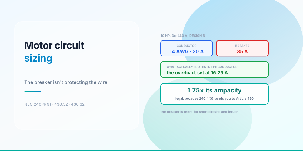
Here is a motor circuit that looks like a serious violation and is entirely correct.
A 10 HP three-phase 460 V motor: 14 AWG copper conductors, rated 20 A, protected by a 35 A breaker. That’s 1.75× the conductor’s ampacity - and on any ordinary branch circuit 240.4(D) would have capped 14 AWG at 15 A, so this is more than double what you’d normally be allowed.
It’s legal because 240.4(G) routes motor circuits out of the normal overcurrent rules entirely and into Article 430. And the reason that’s safe is the part worth understanding: the breaker isn’t protecting the conductor. The overload device is.
Four Devices, Four Jobs
Four devices, four different jobs
A motor circuit contains four protective functions, and conflating them is what makes the arithmetic look wrong:
The disconnecting means (Article 430 Part IX) - lockable, in sight of the motor, rated at least 115% of the FLC. It protects people working on the equipment.
The branch-circuit overcurrent device (430.52) - the 35 A breaker. Its job is short circuits and ground faults only. It has to be large enough to survive starting inrush without tripping, which is why it’s so far above the running current.
The controller (Part VII) - the contactor or starter that switches the motor.
The overload device (430.32) - set at 16.25 A here. This is what protects the conductor and the motor windings against sustained overcurrent. It’s a thermal device sized from the nameplate, and it opens long before 14 AWG is in any danger.
So the conductor has continuous protection at 16.25 A - comfortably below its 20 A rating - while the 35 A device sits upstream waiting for a fault. Nothing is unprotected. The functions are just split across two devices instead of combined into one, which is the whole design philosophy of Article 430.
Note also that the EGC is keyed to the 35 A device, giving 10 AWG copper from Table 250.122 - larger than the 14 AWG phase conductors. That looks odd and is correct, because Table 250.122 reads off the overcurrent device rating, not the load. See Ground Wire Size Chart.
The Device Type Changes Everything
The device type changes the answer sevenfold
| Device | Table 430.52 | Ceiling | Selected | EGC |
|---|---|---|---|---|
| Dual-element (time-delay) fuse | 175% | 24.5 A | 20 A | 12 AWG |
| Inverse-time breaker | 250% | 35.0 A | 35 A | 10 AWG |
| Non-time-delay fuse | 300% | 42.0 A | 40 A | 10 AWG |
| Instantaneous-trip breaker | 1100% | 154.0 A | 150 A | 6 AWG |
20 A to 150 A on the same motor. The device type is the most consequential choice in the circuit, and it’s decided by how the device behaves during the two seconds of inrush rather than by anything about the motor’s running current.
Three things to notice.
The inverse-time breaker’s 250% lands exactly on 35 A - a standard 240.6(A) rating with nothing wasted. That tidiness is part of why it’s the default choice.
Round down, not up. Table 430.52 gives a maximum, so you take the largest standard rating at or below the ceiling. 42.0 A becomes 40 A, not 45 A. This is the opposite of the normal branch-circuit habit and a common error.
The instantaneous-trip breaker’s 1100% is not a free pass. 430.52(C)(3) only permits it as part of a listed combination motor controller, because a device with no time delay will trip on inrush unless it’s coordinated with the overload as an engineered assembly. Design B gets 1100% where other types get 800%, because its inrush is higher.
When the motor still won’t start
430.52(C)(1) Exception No. 2 raises the ceiling where the Table 430.52 value isn’t enough to start the motor:
| Device | Exception ceiling | On this motor |
|---|---|---|
| Inverse-time breaker (≤ 100 A FLC) | 400% | 56 A |
| Non-time-delay fuse | 400% | 56 A |
| Dual-element fuse | 225% | 32 A |
This is a ceiling for a real starting problem, not a default. Reach for it when a correctly sized device demonstrably trips on starting - and check the LRA first, because a motor that won’t start on 250% may have a mechanical problem rather than a protection problem.
Complete Circuits
Complete circuits, and where the ground outgrows the phases
| Motor | FLC | Conductor | Device | EGC | Drop, 100 ft |
|---|---|---|---|---|---|
| 5 HP | 7.6 A | 14 AWG | 15 A | 14 AWG | 0.90% |
| 10 HP | 14 A | 14 AWG | 35 A | 10 AWG | 1.65% |
| 25 HP | 34 A | 8 AWG | 80 A | 8 AWG | 1.00% |
| 50 HP | 65 A | 4 AWG | 150 A | 6 AWG | 0.76% |
Voltage drop is a non-issue on these circuits - under 2% at 100 feet throughout, because 460 V and modest currents are a forgiving combination. Motor circuits are one of the few places where ampacity really is the only conductor constraint, which is the opposite of the situation on long 120 V branch circuits.
14 AWG covers everything up to 10 HP at 460 V. As noted in Motor Full Load Amps, that’s code-legal and most installers still run 12 AWG minimum for mechanical robustness. Sensible, not required.
The Sizing Sequence
Work it in this order and nothing gets missed:
1. Get the FLC from the table. Table 430.250 for three-phase, 430.248 for single-phase - not the nameplate. 430.6(A)(1).
2. Conductors at 125% of table FLC. 430.22. Ignore 240.4(D); 240.4(G) exempts you.
3. OCPD from Table 430.52, by motor type and device type, rounded down to a standard rating.
4. Overload from the nameplate, at 125% (service factor ≥ 1.15 or 40 °C rise) or 115% otherwise, with a 140% ceiling under 430.32(C).
5. EGC from Table 250.122, keyed to the OCPD rating you just selected.
6. Disconnect at 115% of FLC minimum, lockable, and located per 430.102.
7. Check voltage drop - usually a formality at 460 V, occasionally not on a long run to a well pump or a yard machine.
Feeders and Multiple Motors
430.24 sizes a feeder serving several motors at 125% of the largest motor’s FLC plus the sum of all the others’ FLCs. The 125% applies once. It exists to cover whichever motor starts last, on the assumption the rest are already running.
430.62 sizes the feeder’s overcurrent device at the largest branch-circuit device plus the sum of the other motors’ full-load currents. Note the asymmetry: the feeder conductor rule uses 125% of the largest FLC, while the feeder device rule uses the largest branch device - which is a much bigger number.
Tap conductors feeding an individual motor from a feeder follow 430.28, which has its own length and ampacity allowances.
Genuine Traps
Rounding the OCPD up. Table 430.52 is a maximum. 42.0 A → 40 A.
Using an instantaneous-trip breaker outside a listed combination controller. 430.52(C)(3) doesn’t permit it.
Forgetting the overload entirely on a circuit protected only by a breaker. A motor on a 35 A breaker with no overload has 14 AWG protected at 35 A, which is a violation - the exemption from 240.4(D) is conditional on the overload existing.
Assuming the overload is in the breaker. It usually isn’t. It’s in the starter, or it’s an internal thermal protector in the motor (in which case the motor is marked “thermally protected”).
A VFD changes the rules. Article 430 Part X applies, and the drive’s own documentation governs conductor and protection sizing on the output side. Don’t apply Table 430.52 to a drive output.
Air-conditioning equipment is Article 440, not 430. Use the nameplate MCA and MOCP; 440.22 does the same job as 430.52 but the numbers come off the unit. This is the version of the rule most people meet - see 10 Gauge Wire Amps.
Common Mistakes
- Rounding the OCPD up to the next standard rating. Table 430.52 gives a ceiling; round down.
- Applying 240.4(D) to motor conductors. 240.4(G) exempts them, which is the whole point.
- Omitting the overload. The 240.4(D) exemption depends on it existing.
- Sizing the OCPD from the nameplate. 430.52 uses the table FLC.
- Sizing the overload from the table. 430.32 uses the nameplate.
- Using Exception No. 2 as the default. It’s for a motor that demonstrably won’t start.
- An instantaneous-trip breaker on its own. Needs a listed combination controller.
- Applying 125% to every motor on a feeder. 430.24 applies it once, to the largest.
- Sizing the EGC from the conductors. Table 250.122 keys off the device, which is why it can be larger.
- Treating a VFD or an A/C unit as an ordinary motor. Part X and Article 440 respectively.
Size a Motor Circuit
Motor Circuit Calculator - enter horsepower, phase, voltage, motor type, device type and nameplate current. It returns the conductor, the Table 430.52 ceiling and the standard rating below it, the overload setting and maximum, the EGC from Table 250.122, and the voltage drop - with the Exception No. 2 ceiling shown separately.
Start with the Motor FLA Calculator and see Motor Full Load Amps for the table-versus-nameplate rule. For the supply side, Transformer Sizing and Available Fault Current; for starting current, What Size Generator Do I Need.
Sources & standards: NEC (NFPA 70) 2023 - 240.4(D), 240.4(G), 430.6(A)(1), 430.22, 430.24, 430.28, 430.32 and 430.32(C), 430.52 with Table 430.52 and 430.52(C)(1) Exception No. 2 and 430.52(C)(3), 430.62, 430.102, Article 430 Parts VII, IX and X, Article 440 including 440.22, Table 250.122, Tables 430.248 and 430.250. Local amendments override the model code and the AHJ has final say. Have motor circuits designed and installed by a licensed electrician under permit.
FAQ
Why can a 35 amp breaker protect 14 AWG wire on a motor circuit?
Because 240.4(G) routes motor branch-circuit conductors to Article 430 instead of the normal overcurrent rules, which switches off 240.4(D)‘s 15 A cap on 14 AWG. The breaker’s job is short circuits and surviving starting inrush; the overload device - set at 16.25 A here, below the conductor’s 20 A rating - is what protects the conductor against sustained overcurrent. Remove the overload and the arrangement becomes a genuine violation.
How do I size a motor branch-circuit overcurrent device?
From Table 430.52, by motor type and device type, applied to the table full-load current - then round down to the nearest standard rating. For a Design B motor with an inverse-time breaker that’s 250%: 14 A × 2.50 = 35.0 A, which happens to be a standard rating exactly. A non-time-delay fuse at 300% gives 42.0 A, which rounds down to 40 A.
Do I round the motor OCPD up or down?
Down. Table 430.52 states a maximum permitted rating, so you take the largest standard rating at or below the calculated ceiling. This is the opposite of ordinary branch-circuit practice, where you round a continuous load up to the next standard rating, and it’s a frequent source of error.
What is NEC 430.52 Exception No. 2?
An allowance to raise the overcurrent device where the Table 430.52 value is not sufficient to start the motor - to 400% for an inverse-time breaker with an FLC of 100 A or less, 400% for a non-time-delay fuse, and 225% for a dual-element fuse. On a 14 A motor that’s 56 A instead of 35 A. It’s a ceiling for a demonstrated starting problem, not a default, and a motor that won’t start at 250% is worth investigating mechanically first.
Does a motor need both a breaker and an overload?
Yes, and they do different jobs. The branch-circuit device handles short circuits and ground faults and must ride through inrush. The overload device handles sustained overcurrent and protects both the motor windings and the conductors. Some motors are marked “thermally protected,” meaning the overload function is built in - otherwise it’s in the starter.
Why is the ground wire bigger than the circuit conductors?
Because Table 250.122 sizes the equipment grounding conductor from the overcurrent device rating, not from the phase conductors - and on a motor circuit the device runs far above the conductor ampacity. A 10 HP motor on 14 AWG with a 35 A device needs a 10 AWG copper EGC. It looks wrong and it’s correct.
How do I size a feeder for multiple motors?
NEC 430.24 for the conductors: 125% of the largest motor’s full-load current plus the sum of the full-load currents of all the others. NEC 430.62 for the feeder device: the largest branch-circuit device rating plus the sum of the other motors’ full-load currents. Note that these two rules use different bases, so the device is sized from a considerably larger figure than the conductor.
Does this apply to air conditioners and VFDs?
No. Air-conditioning and refrigeration equipment falls under Article 440, where you use the nameplate minimum circuit ampacity for the conductor and the maximum overcurrent protective device rating for the breaker - 440.22 does the job Table 430.52 does for motors. Variable-frequency drives fall under Article 430 Part X, and the drive manufacturer’s documentation governs the output side.