
Voltage Drop: How to Calculate It and What the NEC 3% Rule Really Says
- 03 Aug, 2026
Let’s clear up the thing that causes the most arguments on job sites: the NEC does not require you to keep voltage drop under 3%. Not for ordinary branch circuits, anyway. The 3% and 5% figures everybody quotes live in informational notes - to 210.19(A) for branch circuits and 215.2(A) for feeders - and Article 90 is explicit that informational notes are explanatory material, not enforceable code.
That’s the pedantic truth. Here’s the practical truth: design to 3% anyway. Several jurisdictions have adopted it as a local amendment, it’s a genuinely sound engineering target, and a few specific applications - sensitive electronic equipment, fire pumps, elevators, EV charging equipment per 625.41 - do carry enforceable requirements. What you shouldn’t do is tell an inspector the NEC mandates 3% on a general-purpose circuit, because it doesn’t.
Now, the arithmetic.
The Formula
The trade approximation, based on conductor area in circular mils:
VD = 2 × K × I × L ÷ CM
What each term does
- K - resistivity, 12.9 for copper and 21.2 for aluminum, in ohm-circular-mils per foot
- I - the load in amps actually drawn, not the breaker rating
- L - the one-way run length in feet
- CM - conductor area in circular mils (Chapter 9, Table 8): 6,530 for 12 AWG, 16,510 for 8 AWG, 26,240 for 6 AWG
- 2 - current goes out and comes back. For a balanced three-phase circuit, replace the 2 with 1.732 (√3)
Then convert to a percentage: drop % = VD ÷ circuit voltage × 100.
The most useful thing to notice is that voltage doesn’t appear in the drop formula. The volts lost in a given conductor depend only on material, current, distance, and area. Voltage only enters when you turn those volts into a percentage - which is exactly why a 240-volt circuit tolerates twice the run length of a 120-volt one carrying the same current.
A note on precision: this circular-mil method ignores conductor reactance and temperature effects. For everyday branch circuits and feeders it’s within a couple of percent of the rigorous answer and it’s what the trade uses. For long runs of large conductors, high-power-factor-critical work, or anything where you’re close to a limit, use the resistance and reactance values from Chapter 9, Table 9 instead.
What the Code Actually Says
The 5% budget and how it splits
The recommendation is 3% maximum on a branch circuit and 5% maximum combined from the service to the outlet. The conventional way to spend that is 2% on the feeder and 3% on the branch, but nothing obliges you to split it that way - if your feeder is 20 feet and your branch circuit is 180 feet, put the budget where the distance is.
Worth knowing: 310.15(A) does contain enforceable text on this - it says conductors sized for ampacity per that section don’t automatically satisfy voltage drop, which is the code’s way of telling you these are two separate obligations. And Table 310.12’s 83% dwelling allowance comes with a reminder that voltage drop still has to be checked separately.
Three Worked Examples
A 50-amp circuit, 100 feet, 240 V, copper
The ampacity answer is 8 AWG - exactly 50 A at 75 °C. Check the drop:
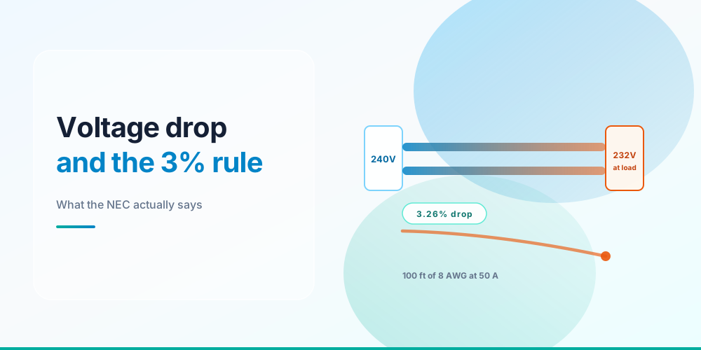
VD = 2 × 12.9 × 50 × 100 ÷ 16,510 = 7.81 V → 7.81 ÷ 240 = 3.26%
Over target, and the load sees 232 V instead of 240. Step to 6 AWG:
VD = 2 × 12.9 × 50 × 100 ÷ 26,240 = 4.92 V → 2.05% ✓
6 AWG copper. One size up from what ampacity alone demanded.
A 20-amp circuit, 150 feet, 120 V, copper
This is the detached-garage scenario, and it’s ugly. 12 AWG passes ampacity comfortably:
VD = 2 × 12.9 × 20 × 150 ÷ 6,530 = 11.85 V → 9.88%
The load sees 108 volts. To get under 3% you need 3.6 V or less, which means at least 21,500 circular mils - and the smallest conductor that clears that is 6 AWG at 26,240 cmil (2.95 V, 2.46%). Two full sizes up from the ampacity answer.
Or you feed the same power at 240 V, which halves the current to 10 amps: the very same 12 AWG then drops 5.93 V, or 2.47%, and passes. Which brings us to the cheapest fix available, below.
A 100-amp three-phase feeder, 300 feet, 208 V, copper
Ampacity says 3 AWG (100 A at 75 °C). Three-phase, so the multiplier is 1.732:
VD = 1.732 × 12.9 × 100 × 300 ÷ 52,620 = 12.74 V → 6.12%
Badly over. Working up: 1/0 gives 6.35 V, or 3.05% - missing by five hundredths of a percent, which is the kind of result that makes you check your arithmetic twice. 2/0 gives 5.04 V, or 2.42% ✓
2/0 copper - three sizes above the ampacity answer. Long runs at 208 V are where voltage drop gets genuinely expensive.
Why It Matters at the Load
What 10% low voltage costs
Undervoltage costs more than the percentage suggests, because most loads don’t respond linearly. Power in a resistive load follows V², so 10% low voltage means 19% less heat out of an element. Motor torque follows V² as well - and worse, a motor holding its mechanical load draws more current at lower voltage, so the windings heat up and the service life shortens. It’s a slow, invisible failure mode, which is why chronically undervolted motors die young for no apparent reason.
Four Ways to Fix a Failing Run
Go up a size. Doubling the circular mils halves the drop. Straightforward, and usually the answer.
Raise the voltage. The single most effective lever. Moving a load from 120 V to 240 V halves the current and doubles the allowable volts - cutting drop percentage to a quarter. That garage circuit above goes from 9.88% to 2.47% at 240 V on the very same 12 AWG.
Shorten the run. Obvious, and occasionally practical: route the feeder more directly, or put a subpanel closer to the loads and feed it once at higher voltage.
Split the load. Two circuits carrying half the current each drop half as much, and the second one gives you spare capacity.
Note that upsizing for voltage drop usually means upsizing the equipment grounding conductor too - 250.122(B) requires the EGC to be increased proportionally when the ungrounded conductors are enlarged. The Ground Wire Size Calculator handles that bump.
Aluminum Drops More
K is 21.2 for aluminum against 12.9 for copper, so an aluminum conductor of the same gauge drops about 64% more voltage. Size aluminum up for ampacity first - one to two trade sizes, per the Wire Size Chart - then re-run the drop calculation on whatever size you landed on, because the ampacity bump often isn’t enough on its own.
Check Your Run
Voltage Drop Calculator - enter conductor, load, length, and phase; get volts lost, percentage, voltage at the load, and the longest run that stays within target.
The Voltage Drop Calculator checks a conductor you already have in mind. If you’d rather work the other direction and have the size picked for you, the Wire Size Calculator runs the ampacity and drop tests together and returns whichever governs - the full method is in What Size Wire Do I Need.
Sources & standards: NEC (NFPA 70) 2023 - 210.19(A) and Informational Notes, 215.2(A) and Informational Notes, 310.15(A), Table 310.12, Chapter 9 Tables 8 and 9, 250.122(B), 625.41. Local amendments override the model code, and the AHJ has final say.
FAQ
Does the NEC require voltage drop to be under 3%?
Not for general branch circuits. The 3% branch and 5% total figures appear in informational notes to 210.19(A) and 215.2(A), and informational notes are explanatory material rather than enforceable requirements. Some jurisdictions adopt them as local amendments, and certain applications - fire pumps, elevators, EV supply equipment - do have enforceable limits. Design to 3% regardless; just don’t misquote the code.
How do I calculate voltage drop?
Use VD = 2 × K × I × L ÷ CM, where K is 12.9 for copper or 21.2 for aluminum, I is the load in amps, L is the one-way run in feet, and CM is the conductor area in circular mils. Replace the 2 with 1.732 for three-phase. Divide the result by the circuit voltage for the percentage.
What is K in the voltage drop formula?
K is the resistivity of the conductor material in ohm-circular-mils per foot: 12.9 for copper and 21.2 for aluminum. It bundles the material’s resistance into a single constant so the formula works directly from circular mils.
Do I use one-way or round-trip distance?
Enter the one-way run length. The factor of 2 in the formula already accounts for the current travelling out and back, so doubling the distance yourself would double-count it and give you twice the real drop.
How far can I run 12 gauge wire on a 20 amp circuit?
About 45 feet at 120 V and about 91 feet at 240 V before drop reaches 3% at a full 20-amp load. At lighter loads it goes considerably farther, since drop is directly proportional to current - 10 amps doubles those figures.
Does voltage drop matter more on 120 V or 240 V?
120 V, by a wide margin. The volts lost in the conductor are identical, but they represent twice the percentage of a 120-volt supply. Moving a load to 240 V also halves the current, so the drop percentage falls to roughly a quarter - the same wire, four times better.