
Motor Full Load Amps: Why You Use Table 430.250, Not the Nameplate
- 04 Aug, 2026
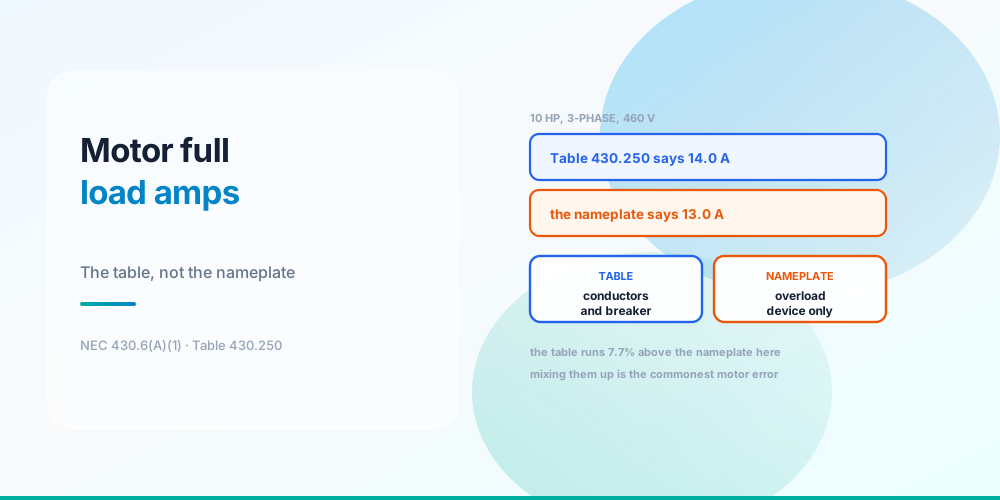
There’s a motor on the wall with 13.0 A printed on its nameplate. NEC Table 430.250 says a 10 HP three-phase motor at 460 V draws 14.0 A. Which number do you use?
Both - for different things, and that’s the rule people get wrong.
- Conductors and the overcurrent device use the table value. 430.6(A)(1) says so explicitly: the values in Tables 430.247 through 430.250 “shall be used instead of the actual current rating marked on the motor nameplate.”
- The overload device uses the nameplate. 430.32 sizes overload protection from the motor’s marked full-load current.
Use the nameplate for the conductors and you undersize them. Use the table for the overload and you leave the motor running hotter than its protection assumes. Both errors are common and both are avoidable by knowing which section governs which calculation.
Two Numbers, Four Calculations
Two current values, and they are not interchangeable
| Calculation | Code | Uses | Result |
|---|---|---|---|
| Branch-circuit conductors | 430.22 | Table | 14 × 1.25 = 17.50 A |
| Overcurrent device | 430.52 | Table | 14 × 250% = 35.0 A ceiling |
| Overload device | 430.32 | Nameplate | 13.0 × 125% = 16.25 A |
| Overload absolute maximum | 430.32(C) | Nameplate | 13.0 × 140% = 18.20 A |
On this motor the table sits 7.7% above the nameplate, which is typical. The gap exists because table values are generalised across the product class rather than measured on one machine.
Two details in that table worth holding onto.
17.50 A gives you 14 AWG copper, which looks alarming next to a 35 A breaker. It’s correct: 14 AWG is rated 20 A at 75 °C, comfortably above 17.50 A, and 240.4(D)‘s 15 A cap on 14 AWG does not apply because 240.4(G) routes motor circuits to Article 430 instead. That’s the subject of Motor Circuit Sizing. In practice most people run 12 AWG as a minimum for mechanical robustness, and that’s a sensible choice rather than a code requirement.
The overload has both a target and a ceiling. 125% is the normal setting for a motor marked with a service factor of 1.15 or greater or a temperature rise of 40 °C or less; 430.32(C) permits going up to 140% where the motor won’t start or carry its load at the lower setting. 16.25 A is the design figure, 18.20 A the limit.
The Ladder
Voltage and phase do most of the work
| Motor | Table FLC | Conductor | Device |
|---|---|---|---|
| 1 HP, 1φ 115 V | 16 A | 14 AWG | 40 A |
| 5 HP, 3φ 460 V | 7.6 A | 14 AWG | 15 A |
| 10 HP, 1φ 230 V | 50 A | 6 AWG | 125 A |
| 10 HP, 3φ 460 V | 14 A | 14 AWG | 35 A |
| 50 HP, 3φ 460 V | 65 A | 4 AWG | 150 A |
The two 10 HP rows are the striking comparison: 50 A single-phase against 14 A on three-phase 460 V. Same mechanical output, 6 AWG versus 14 AWG, and a 125 A device versus a 35 A one. That’s why anything of size runs three-phase where three-phase exists, and it’s the arithmetic behind Three-Phase Power.
Note also that a 1 HP single-phase motor at 115 V draws 16 A - more than a 10 HP three-phase motor at 460 V. Horsepower alone tells you almost nothing about current.
Where the Tables Live
Four tables, and picking the wrong one is easy:
| Table | Covers |
|---|---|
| 430.247 | DC motors |
| 430.248 | Single-phase AC motors |
| 430.249 | Two-phase AC motors |
| 430.250 | Three-phase AC motors |
All are indexed by horsepower and voltage. Read across the voltage column that matches your system: 460 V, not 480 V. The tables use motor nameplate voltages - 115, 200, 208, 230, 460, 575 - which sit slightly below the nominal system voltages of 120, 208, 240, 480 and 600. A 480 V system runs 460 V motors, and you read the 460 V column.
One useful property, worth knowing because it’s a good sanity check: the values scale inversely with voltage. The 460 V column is very close to half the 230 V column throughout, because the same power at double the voltage is half the current.
Why a Table At All
Why two sources, and where it gets awkward
The reasoning matters because it tells you when to be careful.
Conductors use the table because the circuit outlives the motor. A motor gets replaced; the conductors in the wall don’t. If the branch circuit were sized to one machine’s nameplate, the next motor of the same rating - from a different manufacturer, with a different nameplate - might not fit the wire. The table bounds the whole product class, and it lets the circuit be designed before the motor is even selected.
The overload uses the nameplate because it protects one specific machine. An overload device has to trip at the thermal limit of the motor actually installed. Setting it from a generic table value would let the real motor run above its own limit, which is the entire failure mode overload protection exists to prevent.
And here’s the case that catches people: sometimes the nameplate exceeds the table. High-efficiency and inverter-duty motors occasionally have marked currents above the table figure. 430.6(A)(1) still sends you to the table for the conductor and device - but 430.22 also requires the conductors to have adequate ampacity for the load, so if the nameplate is higher, size to the nameplate. Take the larger of the two and you’re never wrong.
The Other Nameplate Fields
Three more markings that do real work:
Service factor. 1.15 or greater qualifies the motor for the 125% overload setting rather than 115%. A motor with no service factor marking and no temperature-rise marking gets 115% - a meaningfully tighter setting, and easy to miss.
Locked-rotor amps (LRA) or code letter. This is the inrush figure, typically 4–6× the running current. It doesn’t enter the FLC calculation but it’s what decides whether the 250% device will actually hold on starting, and it’s the number that matters for generator sizing - see What Size Generator Do I Need.
Design letter. Design B is the energy-efficient squirrel-cage type and by far the most common; it gets a higher instantaneous-trip allowance (1100% versus 800%) in Table 430.52 because its inrush is higher. Wound-rotor and DC motors get much lower percentages across the board.
Multiple Motors and Special Cases
Several motors on one feeder. 430.24 sizes the feeder at 125% of the largest motor’s FLC plus the sum of the others’ FLCs - the 125% applies once, not to every motor.
Duty cycle. 430.22(E) allows reduced conductor sizing for short-time, intermittent and varying-duty motors, with percentages from Table 430.22(E). A crane or a valve actuator doesn’t need 125% continuous.
Torque motors. 430.6(B): rated current is the locked-rotor current, and the nameplate figure is used directly.
Shaded-pole and permanent-split-capacitor motors driving fans and blowers: 430.6(A)(2) uses the nameplate, not the table. This is the exception most likely to come up in HVAC work.
Multispeed motors use the nameplate current for each speed under 430.22(B).
Common Mistakes
- Using the nameplate for conductors. 430.6(A)(1) requires the table value.
- Using the table for the overload. 430.32 requires the nameplate value.
- Reading the 480 V column. There isn’t one - motors are 460 V, and that’s the column.
- Assuming 125% overload always applies. Without a 1.15 service factor or 40 °C rise marking, it’s 115%.
- Ignoring a nameplate above the table value. Take the larger; 430.22 still requires adequate ampacity.
- Applying 240.4(D) to motor conductors. 240.4(G) exempts them, which is why 14 AWG on a 35 A device is legal.
- Applying 125% to every motor on a feeder. 430.24 applies it once, to the largest.
- Using the table for a shaded-pole or PSC fan motor. 430.6(A)(2) sends those to the nameplate.
- Confusing FLC with LRA. Locked-rotor current is 4–6× higher and matters for starting, not sizing.
Look Up a Motor
Motor FLA Calculator - enter horsepower, phase, voltage and the nameplate current. It returns the Table 430.248/430.250 value, the 125% conductor current with a size, and the overload setting and maximum from the nameplate - keeping the two sources visibly separate.
Then size the rest of the circuit with the Motor Circuit Calculator, and see Motor Circuit Sizing for the overcurrent device, Transformer Sizing for the supply, and the NEC Tables reference for the underlying data.
Sources & standards: NEC (NFPA 70) 2023 - 430.6(A)(1) and (A)(2), 430.6(B), 430.22 and 430.22(B) and (E), 430.24, 430.32 and 430.32(C), 430.52 and Table 430.52, 240.4(D), 240.4(G), and Tables 430.247, 430.248, 430.249 and 430.250. Local amendments override the model code and the AHJ has final say. Have motor circuits designed and installed by a licensed electrician under permit.
FAQ
Do I use the motor nameplate or the NEC table for full load amps?
Both, for different purposes. NEC 430.6(A)(1) requires the table value - Tables 430.247 to 430.250 - for sizing branch-circuit conductors and the overcurrent device. NEC 430.32 requires the nameplate value for setting the overload device. On a 10 HP 460 V motor those are 14.0 A and 13.0 A respectively.
Why does the NEC use a table instead of the nameplate?
Because the circuit outlives the motor. A motor gets replaced, often with a different manufacturer’s unit having a different nameplate, while the conductors stay in the wall. Table values bound the whole product class so the circuit remains adequate, and they let the branch circuit be designed before the specific motor is chosen.
Which table do I use for a three-phase motor?
Table 430.250. Table 430.248 covers single-phase, 430.249 two-phase and 430.247 DC. Read the column matching the motor voltage, not the system voltage - a 480 V system runs 460 V motors, so you read the 460 V column. There is no 480 V column.
What is the full load amps of a 10 HP motor?
It depends entirely on voltage and phase. At 460 V three-phase, Table 430.250 gives 14 A. At 230 V single-phase, Table 430.248 gives 50 A - more than three times as much for the same mechanical output. That’s why the conductor is 14 AWG in one case and 6 AWG in the other.
How do I size the overload for a motor?
From the nameplate current, at 125% where the motor is marked with a service factor of 1.15 or greater or a temperature rise of 40 °C or less, and at 115% otherwise. On a 13.0 A nameplate that’s 16.25 A. NEC 430.32(C) permits increasing to a maximum of 140% - 18.20 A here - where the motor won’t start or carry its load at the lower setting.
What if the nameplate current is higher than the table value?
Take the larger. 430.6(A)(1) still sends you to the table for the conductor and overcurrent device, but 430.22 independently requires the conductors to have adequate ampacity for the actual load. Some high-efficiency and inverter-duty motors do exceed the table, so checking both and using the higher figure is always safe.
How do I size a feeder for several motors?
NEC 430.24: 125% of the largest motor’s full-load current, plus the sum of the full-load currents of all the others. The 125% factor applies once, to the largest motor only - not to each motor. It exists to cover the starting current of whichever motor starts last.
Does the 14 AWG conductor really go on a 35 amp breaker?
Yes, for a motor circuit. 240.4(G) routes motor branch-circuit conductors to Article 430 rather than the normal rules, which switches off 240.4(D)‘s 15 A cap on 14 AWG. The conductor is protected by the overload device set at 16.25 A, while the 35 A breaker is there for short circuits and to survive starting inrush. Most installers still run 12 AWG minimum for mechanical robustness, which is good practice rather than code.