
Power Factor Correction: Sizing Capacitor kVAR and Cutting Demand Charges
- 04 Aug, 2026
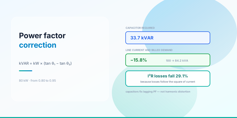
Power factor correction is one formula:
kVAR = kW × (tan θ₁ − tan θ₂)For an 80 kW load going from 0.80 to 0.95 power factor: 80 × (0.7500 − 0.3287) = 33.7 kVAR. That’s the capacitor.
What it buys is worth being precise about, because two of the three benefits get overstated and one gets forgotten. Line current falls 15.8%. I²R losses fall 29.1% - because losses follow the square of current. And kWh consumption barely changes at all, which is the one people expect and don’t get.
What Correction Actually Does
Same 80 kW of work, less current to deliver it
A capacitor supplies reactive power locally, so the source doesn’t have to. Drawn as a power triangle, the base - real power - is unchanged, the vertical side shortens, and the hypotenuse follows it down:
| Before | After | |
|---|---|---|
| Real power | 80 kW | 80 kW |
| Reactive power | 60.0 kVAR | 26.3 kVAR |
| Apparent power | 100.0 kVA | 84.2 kVA |
| Power factor | 0.80 | 0.95 |
The work being done doesn’t change. The motors turn at the same speed doing the same job. What changes is that 33.7 kVAR of the magnetising current now sloshes between the capacitor and the motor instead of travelling back to the transformer every cycle.
The power triangle itself, and why kVA is the number that sizes equipment, is in kVA vs kW.
Where the money comes from
A demand charge billed in kVA. If your utility bills peak demand in kVA rather than kW, a 15.8% cut in apparent power is a 15.8% cut in the billed quantity, directly.
A power-factor penalty. Many tariffs apply a surcharge below a threshold, commonly 0.90 or 0.95. Crossing the threshold removes the penalty entirely, which makes the economics step-shaped rather than linear - and means the right target is usually “just past the threshold,” not unity.
Freed capacity. 15.8% less current in every conductor between the capacitor and the source. On a service running near its limit, that can defer an upgrade - and comparing the cost of capacitors against the cost of a service upgrade is a calculation worth doing before assuming the upgrade. See Electrical Panel Upgrade Cost.
Reduced losses. 29.1% off the I²R losses in your own distribution. Real, but usually the smallest of the four - internal distribution losses are a low single-digit percentage of consumption to begin with.
What you don’t get is a lower kWh bill. Reactive power does no work, so it barely registers on a real-energy meter. The saving is in demand and penalty charges, not consumption. Anyone selling a “power saver” device to a residential customer on the promise of lower kWh is selling nothing - domestic meters register real energy and domestic tariffs don’t charge for power factor.
Why 0.95 and Not Unity
Why 0.95 is the target and unity is not
| Target PF | Capacitor kVAR | Current cut | I²R loss cut |
|---|---|---|---|
| 0.85 | 10.4 | 5.9% | 11.4% |
| 0.90 | 21.3 | 11.1% | 21.0% |
| 0.92 | 25.9 | 13.0% | 24.3% |
| 0.95 | 33.7 | 15.8% | 29.1% |
| 0.98 | 43.7 | 18.4% | 33.4% |
| 1.00 | 60.0 | 20.0% | 36.0% |
Getting from 0.95 to unity costs another 26.3 kVAR - as much again as the entire climb from 0.80 - and buys just 4.2 more points of current reduction. The curve flattens hard, which is the arithmetic reason 0.95 is the industry target.
There’s a safety reason too. Over-correction is worse than under-correction:
- A leading power factor can cause overvoltage at light load, because a capacitor’s current rises with voltage and its reactive contribution doesn’t fall away when the motors stop.
- Capacitors and system inductance form a resonant circuit. Land that resonance near the 5th or 7th harmonic and you get amplified harmonic currents and voltages, which is how correction equipment destroys itself.
- Self-excitation. A capacitor left connected to a motor that has been disconnected from the supply can keep it excited as it coasts, generating voltage on a circuit everyone believes is dead. This is why capacitors at motor terminals must switch with the motor.
Under-correcting to 0.92 and leaving margin is a defensible engineering choice. Aiming at unity is not.
Where to Put Them
The further downstream, the more you unload
At the motor terminals - unloads the branch circuit, the feeder and the service. Maximum benefit, and the capacitor switches with the motor so it can’t over-correct at light load. The constraint is self-excitation: size it to the motor’s no-load magnetising current, not to full-load kVAR, and follow the manufacturer’s table. Never fit capacitors to the load side of a VFD.
At the motor control centre - unloads the feeder and service. Fewer, larger units, easier to maintain, and automatic switching in steps becomes practical. Branch circuits stay fully loaded.
At the service entrance - unloads the utility side only. Simplest to install, fixes a demand bill, and frees no capacity inside the building whatsoever. This is where most correction actually gets installed, which is fine if the goal is purely the bill and a missed opportunity if the goal is capacity.
Automatic capacitor banks switch steps in and out to follow the load, which is the standard answer where load varies a lot and where a fixed bank would over-correct at night.
Harmonics - Where Capacitors Are the Wrong Answer
This is the failure mode worth understanding before specifying anything.
Displacement power factor is current lagging voltage because the load is inductive. That’s the motor case, and capacitors are exactly right for it.
Distortion power factor is current that isn’t sinusoidal, because the load draws in pulses - switch-mode power supplies, VFDs, LED drivers, computers. Total power factor can be poor while displacement power factor is near unity.
Capacitors do nothing for distortion, and they can make it dangerous. A capacitor’s impedance falls as frequency rises, so it’s a low-impedance path for harmonic currents. Combined with system inductance it can resonate at a harmonic frequency and amplify it, overheating the capacitors and everything else on that bus.
So: measure before you specify. A power-quality meter that reports displacement PF, total PF and THD separately tells you which problem you have. If THD is significant, the answer is detuned (harmonic-filtered) capacitor banks with a series reactor, or active filtering - not plain capacitors.
The related conductor consequence is that triplen harmonics add in a wye system’s neutral rather than cancelling, which is why 310.15(E)(2) makes you count it as a current-carrying conductor. See Wire Derating Explained and Three-Phase Power.
Code Requirements
Article 460 covers capacitors. The provisions that come up:
- 460.8(A) - conductors to a capacitor must have an ampacity of at least 135% of the capacitor’s rated current, because capacitors draw more than nameplate on harmonics and overvoltage.
- 460.8(B) - overcurrent protection is required for each capacitor bank, except where the capacitor is connected on the load side of a motor overload device.
- 460.8(C) - a disconnecting means is required, rated at least 135% of the capacitor current.
- 460.6 - stored energy must be drained; capacitors need discharge means and a waiting period before handling.
- 460.9 - where a capacitor is switched with a motor, the total improvement must not raise the voltage above the motor’s rating, and the overload device setting may need revisiting because line current falls after correction.
That last point catches people: correcting a motor changes the current the overload sees, so a correctly set overload can end up mis-set. Article 430’s overload rules are in Motor Circuit Sizing.
Common Mistakes
- Expecting a lower kWh bill. Correction cuts demand and penalties, not real energy consumption.
- Correcting to unity. Costs as much again as reaching 0.95 and risks overvoltage and resonance.
- Using plain capacitors on a harmonic-rich system. They can resonate and amplify. Measure THD first.
- Fitting capacitors at the service and expecting freed capacity inside. They only unload upstream of themselves.
- Sizing motor-terminal capacitors to full-load kVAR. Size to no-load magnetising current to avoid self-excitation.
- Leaving a capacitor connected to a coasting motor. Self-excitation energises a supposedly dead circuit.
- Capacitors on the load side of a VFD. Never.
- Sizing conductors at 100% of capacitor current. 460.8(A) requires 135%.
- Not re-checking the motor overload after correction. Line current changes.
- Selling correction to a residential customer. Domestic meters register kWh and domestic tariffs don’t penalise power factor.
Size the Capacitor
Power Factor Calculator - enter real power, existing power factor and target, and it returns the kVAR required, the before-and-after apparent power and line current, and the reduction in each.
Pair it with the kVA Calculator for the power triangle and the Three-Phase Power Calculator for line quantities. See kVA vs kW for the underlying relationships and Motor Full Load Amps for the loads that create the problem.
Sources & standards: NEC (NFPA 70) 2023 - Article 460 including 460.6, 460.8(A), 460.8(B), 460.8(C) and 460.9; 310.15(E)(2) for harmonic neutral counting. The power-triangle relationships are physics. Utility demand-charge and power-factor-penalty structures vary by utility and tariff - read yours. Resonance, self-excitation and harmonic filtering on a real installation warrant a power-quality survey and, above modest sizes, an engineered design.
FAQ
How do I calculate the capacitor kVAR needed?
kVAR = kW × (tan θ₁ − tan θ₂), where θ₁ and θ₂ are the angles whose cosines are the existing and target power factors. For 80 kW going from 0.80 to 0.95: tan θ₁ = 0.7500 and tan θ₂ = 0.3287, so 80 × 0.4213 = 33.7 kVAR.
Does power factor correction reduce my electricity bill?
It reduces demand charges billed in kVA and removes power-factor penalties, which on a commercial tariff can be substantial. It does not meaningfully reduce kWh consumption, because reactive power does no work and barely registers on a real-energy meter. For a residential customer billed only in kWh, correction saves essentially nothing.
Why is 0.95 the target instead of 1.0?
Because the cost curve steepens sharply. On an 80 kW load, reaching 0.95 from 0.80 needs 33.7 kVAR; getting from there to unity needs another 26.3 kVAR for only 4.2 more points of current reduction. Unity also brings real risks - overvoltage at light load, and resonance between the capacitors and system inductance.
Can power factor correction cause problems?
Yes, three in particular. Over-correction gives a leading power factor and can raise voltage at light load. Capacitors plus system inductance form a resonant circuit, and if that resonance lands near the 5th or 7th harmonic it amplifies harmonic currents destructively. And a capacitor left connected to a motor that has been disconnected can keep it self-excited as it coasts, energising a circuit that appears dead.
Do capacitors fix harmonics?
No - they can make them worse. Capacitors correct displacement power factor, where current lags voltage because of inductive load. They do nothing for distortion power factor caused by non-sinusoidal current from electronic loads, and because a capacitor’s impedance falls with frequency it becomes a low-impedance path for harmonic currents. Harmonic-rich systems need detuned banks with series reactors, or active filtering.
Where should capacitors be installed?
At the motor terminals for maximum benefit, since that unloads the branch circuit, the feeder and the service - but sized to the motor’s no-load magnetising current and switched with the motor to avoid self-excitation. At a motor control centre for a compromise that unloads the feeder and service. At the service entrance if the only goal is the demand bill, since that frees no capacity inside the building.
What size conductors do capacitors need?
At least 135% of the capacitor’s rated current, per NEC 460.8(A). The margin exists because capacitors draw more than their nameplate current in the presence of harmonics and overvoltage. The disconnecting means under 460.8(C) is also rated at 135%.
Will correction change my motor overload setting?
It changes the line current the overload sees, so a correctly set overload can end up mis-set - 460.9 addresses this. Where the capacitor is connected on the load side of the overload device, the overload no longer measures the full motor current. Review the setting after correction rather than assuming it still applies.