
How to Use a Multimeter: Volts in Parallel, Amps in Series
- 06 Aug, 2026
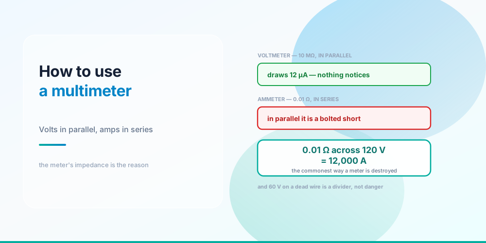
Most multimeter instruction is a tour of the dial. That’s the least useful part, because the dial is obvious and the thing that destroys meters isn’t.
Here is the rule that matters:
Voltmeter  - nearly an open circuit. Goes in PARALLEL, across things.
Ammeter    - nearly a short circuit. Goes in SERIES, inside the loop.
Get that backwards in the dangerous direction - an ammeter placed across a live circuit - and you have deliberately connected a 0.01 Ω shunt straight across the supply. Everything else in this article is easier than that one idea, and nothing else on the meter will hurt you as reliably.
Why the Meter’s Impedance Decides Where It Goes
Volts in parallel, amps in series - and never the other way round
A voltmeter has an input impedance around 10 MΩ. Put it across 120 V and it draws 120 ÷ 10,000,000 = 12 microamps. That’s deliberately negligible: the meter has to observe the circuit without changing it, so it’s built to be as close to an open circuit as practical while still passing enough current to measure.
An ammeter is the opposite. Current has to flow through it to be measured, so it presents a shunt of roughly 0.01 Ω and you must open the circuit and insert the meter into the path. Its whole design goal is to add as little resistance as possible so the circuit behaves as it did before.
Now combine those two facts. Leave the meter in current mode, put the probes across a 120 V circuit the way you would for a voltage reading, and Ohm’s law does the rest:
I = 120 ÷ 0.01 = 12,000 AThe meter has become a bolted fault. What actually happens depends on what the source can deliver - the current jacks are fused precisely for this, and a decent meter’s fuses are high-rupture-capacity sand-filled types rather than glass. But on a circuit with real fault current available, this is how meters explode and how people get hurt. The Available Fault Current post covers how much energy is genuinely on tap at a given point.
Two habits remove the risk almost entirely: return the dial to volts before you put the meter away, and use a clamp meter for current wherever you can, since it never enters the circuit at all.
The Three Measurements
Voltage - circuit live, probes in parallel. Across a load to see what it’s getting, across an open switch to see if it’s blocking, across a suspect connection to see what it’s stealing. That last one is the best diagnostic in the trade: a good termination shows essentially zero, and a 0.5 Ω joint carrying 11.43 A shows 5.71 V - which is also 65 watts of heat at one screw. That arithmetic is worked through in Series vs Parallel Circuits and Ohm’s Law Explained.
Current - circuit live, meter in series, or a clamp around one conductor. In practice, use the clamp. A clamp meter reads the magnetic field around a conductor, so it needs no electrical contact and cannot short anything.
One thing about clamps trips everyone up once: clamp around both conductors of a circuit and you read zero. The hot’s 12 A out and the neutral’s 12 A back produce equal and opposite fields that cancel. That’s not a fault in the meter - it’s exactly the principle a GFCI uses, and it means a clamp around both conductors is a leakage detector. Anything other than zero is current returning by some path that isn’t the neutral. See GFCI vs AFCI and Hot, Neutral and Ground.
Resistance and continuity - circuit dead, always. The meter measures resistance by injecting its own small test current and observing the voltage it produces. Apply an external voltage and the reading is meaningless at best. Two consequences worth internalising: resistance readings on an energised circuit are garbage, and a component in a circuit reads in parallel with everything else connected to it, so isolate at least one end before believing a number.
A resistance check is also a poor test for a bad connection. A failing termination frequently reads acceptable when cold and only misbehaves under load - which is why the voltage-across-it-under-load test beats it every time.
Ghost Voltage Is a Divider, Not a Hazard
Ghost voltage is just a voltage divider
| Coupling impedance | 10 MΩ meter reads | 3 kΩ low-Z meter reads |
|---|---|---|
| 1 MΩ | 109.1 V | 0.36 V |
| 10 MΩ | 60.0 V | 0.04 V |
| 50 MΩ | 20.0 V | 0.01 V |
| 100 MΩ | 10.9 V | 0.00 V |
You disconnect a conductor, check it, and the meter says 60 V. The conductor is dead.
What’s happening is capacitive coupling from a live conductor running alongside it - and the moment your 10 MΩ meter touches it, that coupling and the meter form a voltage divider, the same arrangement as a resistor pair. With roughly 10 MΩ of coupling and a 10 MΩ meter, the two legs are equal and you read half the source: 60 V. It looks alarming and there is essentially no energy behind it.
Switch to a low-impedance meter - a few kΩ, often marked LoZ - and the lower leg of the divider collapses. The same conductor now reads 0.04 V, because the meter loads the coupling to nothing. A solenoid-type tester does the same thing mechanically.
The catch is that this cuts both ways, and it’s why you never conclude “dead” from one reading. A high-impedance meter can show voltage that isn’t there; used carelessly it can also be misread. The discipline is live–dead–live: prove the meter on a known live source, test the conductor, then prove the meter again on the known live source. If the meter failed between the first and third step, you find out before it matters - and no single reading is doing the work of a decision.
CAT Ratings Are About Where, Not Volts
The CAT rating says where, not how much voltage
| Category | Where it applies | Examples |
|---|---|---|
| CAT IV | Origin of the installation | Service drop, meter socket, service entrance, outdoor conductors |
| CAT III | Fixed distribution | Panelboards, feeders, hard-wired equipment, motor controls |
| CAT II | Receptacle-connected loads | Appliances, portable tools, anything on a cord and plug |
| CAT I | Protected electronics | Secondary circuits isolated from the mains |
The number beside CAT is not the interesting part. The category describes how much transient energy is available where the probe lands, and that rises the closer you get to the source. A surge that a branch circuit’s impedance would soften arrives at the service entrance with very little standing in its way.
Which produces the fact people get wrong: CAT III 600 V is a more demanding rating than CAT II 1000 V. The category is tested with a lower source impedance as well as a transient withstand level, so a higher category means the instrument survives more delivered energy - not merely more volts. Choosing a meter by the voltage number alone is choosing the wrong axis.
Practically: work inside a panel and you want CAT III minimum; work at the service, meter socket or outdoors and you want CAT IV. The leads and probes carry their own ratings, and the assembly is only as good as its weakest part - a CAT IV meter with CAT II leads is a CAT II tool.
What the Meter Won’t Tell You
It won’t tell you a circuit is safe to work on. It tells you what it measured, at one point, at one instant. Lock-out/tag-out and a live–dead–live proving sequence do the actual work.
It won’t reveal a bootleg ground. A neutral jumpered to the ground screw reads as a correctly wired receptacle on a plug-in tester and gives sensible voltages on a meter, because the two conductors are bonded at the service anyway. Finding it takes inspection.
It won’t measure a distorted waveform correctly unless it’s true RMS. An averaging meter scales its reading by a form factor that’s only right for a clean sine, so LED drivers, variable frequency drives and switching supplies can read significantly low - see AC vs DC.
It won’t find an intermittent connection you aren’t loading. Bad joints read fine cold. Put the circuit under load and measure the drop across the connection.
And it is not personnel protection. A meter observes; it doesn’t intervene. The device that protects a person is a GFCI at 4–6 mA, as Where GFCI Is Required covers.
Common Mistakes
- Leaving the dial in amps. Probing a live circuit in current mode puts a 0.01 Ω shunt across the supply. Return the dial to volts every time.
- Measuring current in parallel. Current measurement requires opening the circuit - or a clamp, which is better.
- Measuring resistance on a live circuit. The meter injects its own test current; external voltage makes the reading meaningless and can damage it.
- Believing ghost voltage. 60 V on a disconnected conductor is a divider between coupling and a 10 MΩ input. Confirm with a low-Z meter.
- Declaring dead from one reading. Live–dead–live, on a known source, every time.
- Clamping both conductors and expecting a load reading. The fields cancel to zero - that configuration reads leakage, not load.
- Choosing a meter by voltage instead of category. CAT III 600 V outranks CAT II 1000 V; match the category to where the probe lands.
- Pairing a CAT IV meter with lower-rated leads. The assembly takes the lowest rating in it.
- Trusting a cold resistance check on a suspect joint. Measure the voltage across it under load instead.
Run the Numbers
Ohm’s Law Calculator - every reading on this page is V = IR applied to something, including the meter itself.
To turn a measured current into a load figure, use the Amps to Watts Calculator, and to check a measured drop against a design target the Voltage Drop Calculator and Conductor Resistance Calculator. A clamp-meter reading of a panel’s actual peak demand is the input to the Existing Load Calculator - the 220.87 method covered in NEC 220.87 Existing Load, and the strongest argument against an unnecessary panel upgrade. What the breaker does with the current you measure is in How a Circuit Breaker Works.
Sources & standards: Ohm’s law and voltage-divider behaviour are physics. Input impedance of about 10 MΩ for a digital voltmeter, a current shunt on the order of 0.01 Ω, and a low-impedance mode of a few kΩ are representative figures - check the specification for the instrument in hand, as they vary by model and range. Measurement categories CAT I to CAT IV are defined in IEC 61010; this page describes what each category covers and deliberately does not publish the transient test values, which differ by category and voltage and should be read from the standard or the instrument’s own documentation. GFCI thresholds of 4–6 mA are UL 943 Class A. Live–dead–live proving and lock-out/tag-out practice follow NFPA 70E; the NEC itself does not govern work procedure. A licensed electrician and the authority having jurisdiction have final say on anything installed.
FAQ
How do you measure voltage with a multimeter?
Set the dial to volts, choose AC or DC to match the circuit, and place the probes in parallel - across the two points you want the difference between. The circuit stays live. A voltmeter has around 10 MΩ of input impedance so it draws only about 12 microamps at 120 V, which is deliberately negligible: it has to observe the circuit without altering it.
Why does an ammeter go in series?
Because current has to flow through the meter to be measured. That means opening the circuit and inserting the meter into the path, which is why an ammeter is built with a shunt of roughly 0.01 Ω - it must add as little resistance as possible so the circuit behaves as it did before. A clamp meter avoids the whole problem by reading the magnetic field around a conductor instead.
What happens if you measure amps in parallel?
You place the meter’s 0.01 Ω shunt directly across the supply, which is a deliberate short circuit - 120 ÷ 0.01 is 12,000 amps if the source can deliver it. This is the single commonest way meters are destroyed, and on a circuit with real fault current available it is genuinely dangerous. The current jacks are fused for it, but the reliable fix is habit: return the dial to volts before putting the meter down.
Why does my meter show voltage on a disconnected wire?
Capacitive coupling from a live conductor running alongside it. The moment a 10 MΩ meter touches the dead conductor, the coupling and the meter form a voltage divider - with roughly equal impedances you read about half the source, so 60 V on a 120 V system. There is almost no energy behind it. Confirm with a low-impedance meter, which loads the coupling down to a fraction of a volt.
What is low impedance or LoZ mode for?
Rejecting ghost voltage. A LoZ mode drops the meter’s input impedance from around 10 MΩ to a few kΩ, which collapses the divider that capacitive coupling forms. The same conductor that read 60 V on the high-impedance range reads about 0.04 V on LoZ. A solenoid-type tester achieves the same result mechanically, which is why those never showed ghost voltage in the first place.
Can I measure resistance on a live circuit?
No. The meter measures resistance by injecting its own small test current and reading the resulting voltage, so any externally applied voltage makes the result meaningless and can damage the instrument. De-energise first, and isolate at least one end of the component - anything else still connected to it reads in parallel and drags the number down.
What do CAT III and CAT IV mean on a multimeter?
They describe where in the distribution system the meter may safely be used, based on the transient energy available at that point. CAT IV is the origin of the installation - service drop, meter socket, service entrance. CAT III is fixed distribution: panelboards, feeders, hard-wired equipment. CAT II is receptacle-connected loads. Energy available is highest upstream, so working in a panel wants CAT III minimum and working at the service wants CAT IV.
Is CAT III 600 V better than CAT II 1000 V?
Yes, for most electrical work. The category is tested with a defined source impedance as well as a transient withstand level, so a higher category means the instrument survives more delivered energy rather than simply more volts. Choosing by the voltage number alone selects the wrong axis. Note too that leads and probes carry their own ratings - a CAT IV meter with CAT II leads is a CAT II tool.
Why does my clamp meter read zero around a cable?
Because you’ve clamped around both conductors. The current going out on the hot and returning on the neutral produce equal and opposite magnetic fields that cancel, so the net reading is zero. Clamp one conductor to read load current. That cancellation is exactly the principle a GFCI uses, which means a clamp around both conductors is a useful leakage detector - anything other than zero is current returning by some path that isn’t the neutral.