
AC vs DC: What Alternating Current Actually Means
- 06 Aug, 2026
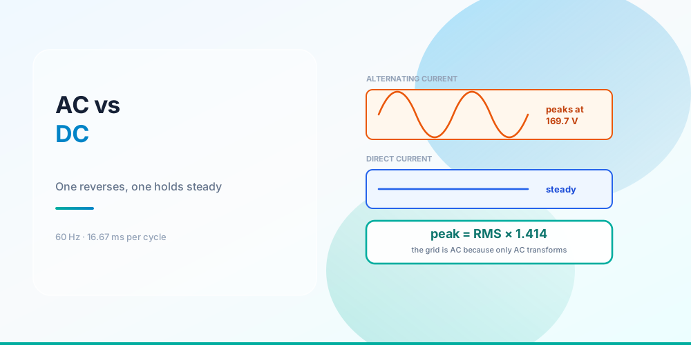
Direct current flows one way. Alternating current reverses direction, sixty times a second in North America.
That’s the textbook answer and it’s correct, but it leaves out the fact that surprises most people learning this: the “120 volts” at your receptacle is not a voltage the circuit ever sits at. It’s a statistical summary of a wave that swings between +169.7 V and −169.7 V, passing through zero 120 times every second.
Understanding what that number actually measures explains a string of things that otherwise look like trivia - why insulation ratings have the margins they do, why a cheap meter lies on some loads, why reactance and power factor exist at all, and why a DC arc is the one that won’t go out.
The Waveform, and Where “120 Volts” Comes From
'120 volts' is an average that never actually appears
RMS stands for root mean square, and it has one job: express an alternating quantity as the DC value that would do the same work.
Take a resistive heater. Its power is I²R, and because current is squared, both halves of the AC cycle heat it - direction doesn’t matter to a resistor. Square the waveform, take the mean of that, take the square root, and you get the DC value that would produce identical heating. For a sine wave that works out to peak ÷ √2, or 0.7071 × peak.
So 120 V RMS and 120 V DC warm the same element by exactly the same amount. That equivalence is the entire reason the number is quoted that way - it lets every formula you know from DC keep working on AC.
Two other averages exist and are worth not confusing:
| Measure | Value for a sine | What it’s for |
|---|---|---|
| Peak | 1.0 × peak | Insulation and semiconductor ratings |
| RMS | 0.7071 × peak | Power, heating, everything on a nameplate |
| Average of the rectified wave | 0.6366 × peak | What cheap meters actually sense |
That last row is a real trap. Inexpensive multimeters measure the rectified average and multiply by the form factor of 1.1107 to display an RMS figure. That works perfectly on a clean sine and gets progressively wrong on anything else - LED drivers, VFDs, switching supplies and dimmers all draw distorted current. On those loads a meter that isn’t marked true RMS can read significantly low.
What the Insulation Sees
What the insulation actually sees
| Nominal (RMS) | Peak | Peak to peak | Where it shows up |
|---|---|---|---|
| 120 V | 169.7 V | 339.4 V | receptacles, lighting |
| 208 V | 294.2 V | 588.3 V | 3φ commercial, line-to-line |
| 240 V | 339.4 V | 678.8 V | dwelling line-to-line |
| 277 V | 391.7 V | 783.5 V | commercial lighting |
| 480 V | 678.8 V | 1,357.6 V | 3φ motors and equipment |
Every one of those peaks is 41.4% above the nominal figure, because peak is always RMS × √2. Insulation is rated in RMS volts by convention, but the dielectric has to hold off the peak every single cycle - the margin built into a 600 V rating is doing real work on a 480 V system.
The 208 V row is worth a second look, because it isn’t 240 V for a reason that has nothing to do with this wave. On a three-phase wye system the line-to-line voltage is 120 × √3 = 207.85 V, because the two phases are 120° apart rather than opposed. That geometry is worked through in Three-Phase Power Calculation, and the split-phase system that gives dwellings a true 240 V is covered in Split-Phase 120/240 V.
Why the Grid Is AC
Why the grid is AC: transformers, and the square law
| Line voltage | Current | I²R loss | Share of the power |
|---|---|---|---|
| 240 V | 417 A | 173.6 kW | 174% - impossible |
| 480 V | 208 A | 43.4 kW | 43% |
| 4.16 kV | 24.04 A | 577.8 W | 0.5778% |
| 13.8 kV | 7.25 A | 52.5 W | 0.0525% |
| 69 kV | 1.45 A | 2.1 W | 0.0021% |
The same 100 kW, the same one ohm of line, and the loss spans five orders of magnitude. Loss is P²R ÷ V², so it falls with the square of the transmission voltage - double the voltage and you quarter the loss.
The top row isn’t a rounding artefact, it’s a genuine impossibility: at 240 V the line would need to dissipate more than the power being delivered, so that circuit simply cannot work over that distance.
Which brings you to the actual reason the grid alternates. A transformer only works on changing magnetic flux. Steady DC produces steady flux, which induces nothing in the secondary. AC changes continuously, so it can be stepped up to transmission voltage, carried a long way at low current, and stepped back down at the point of use - cheaply, passively, with no moving parts and no electronics. In the 1890s nothing could do that to DC at any sensible cost, and that, rather than any safety argument, settled it.
The same square law is why 240 V circuits beat 120 V ones inside a building, and why voltage drop on a long run is a design problem at all - see Voltage Drop.
Where DC Actually Lives Now
The irony is that most of what you plug in runs on DC internally. The AC arrives, and the first thing the device does is rectify it.
Solar arrays are DC until the inverter. A string of modules produces DC at a voltage that varies with temperature, which is why string sizing is its own calculation - see Solar String Sizing.
EV batteries are DC. An AC charger is really a cable feeding the car’s onboard rectifier; DC fast charging skips that and feeds the pack directly, which is the whole reason it’s faster. What Size Wire for an EV Charger covers the AC side of that.
LED lighting is DC. Every LED needs a driver converting AC to a controlled DC current, which is also why LED dimming is fussier than incandescent dimming and why a dimmer’s LED rating is far below its incandescent rating - see How Many Lights on One Circuit.
Control circuits are often 24 V DC, and essentially all electronics run DC after their power supply.
So the modern building is AC in the walls and DC at nearly every endpoint, with a conversion stage at each one.
Frequency Is Not Just a Number
Frequency is the count of complete cycles per second. At 60 Hz each cycle takes 16.67 ms and the polarity reverses 120 times a second. Most of the world runs 50 Hz.
That difference is not cosmetic, because an AC motor’s speed is set by the supply frequency:
synchronous rpm = 120 × frequency ÷ poles| Poles | 60 Hz | 50 Hz |
|---|---|---|
| 2 | 3,600 rpm | 3,000 rpm |
| 4 | 1,800 rpm | 1,500 rpm |
| 6 | 1,200 rpm | 1,000 rpm |
| 8 | 900 rpm | 750 rpm |
An induction motor actually runs a few percent below synchronous speed - that lag is slip, and it’s what produces torque - which is why a 4-pole motor’s nameplate typically reads about 1,750 rpm rather than 1,800. Move that motor to 50 Hz and it runs at five-sixths the speed, which for a fan or pump changes the airflow and the power draw dramatically. Motor nameplate figures and circuit sizing are in Motor Full Load Amps.
A variable frequency drive is simply a device that rectifies the incoming AC to DC and then synthesises AC at whatever frequency it likes - which is how you get variable speed out of a fixed-speed machine.
What Exists Only Because of AC
Several things you deal with constantly have no DC equivalent at all:
Reactance. A changing current in a conductor creates a changing magnetic field that opposes the change. That opposition is inductive reactance, X = 2πfL, and at DC - where f is zero - it vanishes. This is why Chapter 9 has a separate reactance table, and why on large conductors reactance can exceed resistance.
Impedance. With reactance in play, the opposition to current is impedance rather than resistance, and voltage and current stop peaking at the same instant.
Power factor. Once they’re out of phase, volts × amps stops equalling watts. That’s the entire subject of kVA vs kW and Power Factor Correction.
The zero crossing - which turns out to matter for safety. An AC arc is extinguished 120 times a second as the current passes through zero, and a switch or breaker only has to hold the gap open at that moment. A DC arc has no zero crossing, so once drawn it sustains itself and must be actively stretched and cooled until it fails. This is why a device rated for AC cannot be assumed safe on DC, why PV work requires DC-rated disconnects and overcurrent devices under NEC Article 690, and why arc-fault protection on the DC side of a solar array is a specific requirement rather than an option.
Common Mistakes
- Thinking 120 V is the highest voltage present. It peaks at 169.7 V, twice per cycle, every cycle.
- Using an averaging meter on a distorted load. Without “true RMS” on the display, readings on LED drivers, VFDs and dimmers can be well off.
- Assuming any breaker or switch works on DC. No zero crossing means the arc doesn’t self-extinguish. Use DC-rated devices on DC.
- Confusing peak-to-peak with peak. 120 V RMS is 339.4 V peak-to-peak - double the peak.
- Expecting 240 V between two legs of a 208 V system. Three-phase legs are 120° apart, so 120 × √3 = 207.85 V.
- Thinking the grid is AC for safety reasons. It’s AC because transformers need changing flux, and high-voltage transmission cuts I²R loss by the square.
- Applying DC intuition to large conductors. Reactance is negligible at 12 AWG and dominant at 500 kcmil.
- Assuming a motor keeps its speed on a different frequency. Synchronous speed is 120f ÷ poles; 50 Hz costs a sixth of the rpm.
Run the Numbers
Ohm’s Law Calculator - the DC relationships that RMS was defined to preserve, so they work on AC RMS values directly.
For AC-specific work, the Power Factor Calculator and kVA Calculator handle the phase-angle side, the Three-Phase Power Calculator covers the √3 systems, and the Conductor Resistance Calculator shows resistance and reactance separately. For the DC side of a PV array use the Solar String Calculator, and the Unit Converter handles the everyday conversions. The topology those currents flow through is in Series vs Parallel Circuits.
Sources & standards: RMS, peak and average relationships for a sine wave, transformer action and synchronous motor speed are physics rather than code. The √2 and 1.1107 form factors apply to undistorted sinusoids only. Transmission figures are illustrative - 100 kW through 1 Ω of line resistance - chosen to show the square law, not to model a real feeder. DC-rated equipment requirements for photovoltaic systems are NEC (NFPA 70) 2023 Article 690. Nominal system voltages follow ANSI C84.1 conventions. A licensed electrician and the authority having jurisdiction have final say on anything installed.
FAQ
What is the difference between AC and DC?
Direct current flows in one direction at a steady level. Alternating current reverses direction periodically - 60 times a second in North America, 50 in most of the rest of the world. A battery is DC, a receptacle is AC. The practical consequences are that AC can be transformed to a different voltage cheaply and that AC arcs self-extinguish at each zero crossing, while DC does neither.
Why is 120 V AC actually 170 V?
Because 120 V is the RMS value, not the peak. The waveform swings between +169.7 V and −169.7 V, and 120 is the equivalent steady DC value that would produce the same heating in a resistor. Peak is always RMS × √2, so every nominal AC voltage is about 41% higher at its crest than its name suggests.
What does RMS mean?
Root mean square: square the waveform, take the mean of the squared values, then take the square root. It’s defined that way because power depends on current squared, so RMS gives you the DC value that would deliver identical power. For a sine wave it equals 0.7071 × peak. Quoting AC in RMS lets every DC power formula keep working unchanged.
Why is the electrical grid AC instead of DC?
Because transformers only work on changing magnetic flux, so only AC could be stepped up for transmission and back down for use with cheap passive equipment. That matters enormously: line loss is P²R ÷ V², so it falls with the square of voltage. Delivering 100 kW through 1 Ω of line wastes 43% at 480 V but only 0.0525% at 13.8 kV.
Is DC more dangerous than AC?
They’re dangerous in different ways, and neither is casually safe. The clearest practical difference is arcing: AC current passes through zero 120 times a second, giving an arc a chance to extinguish, while DC has no zero crossing so an arc sustains itself until it’s actively stretched and cooled. That’s why switches, breakers and fuses need a specific DC rating, and why photovoltaic work under NEC Article 690 requires DC-rated devices.
Do I need a true RMS meter?
On clean sinusoidal loads, no - an averaging meter scales its reading by the 1.1107 form factor and lands in the right place. On anything that draws distorted current, yes. LED drivers, variable frequency drives, switching power supplies and electronic dimmers all distort the waveform, and an averaging meter can read significantly low on them. Modern buildings are full of those loads.
What is peak-to-peak voltage?
The full swing from the most negative point to the most positive - double the peak value. A 120 V RMS circuit peaks at 169.7 V in each direction, so its peak-to-peak figure is 339.4 V. It’s mostly an oscilloscope term; nameplates and code use RMS.
Why does frequency matter?
Because AC motor speed is set by it: synchronous rpm = 120 × frequency ÷ poles. A 4-pole motor runs at 1,800 rpm synchronous on 60 Hz and 1,500 rpm on 50 Hz. Frequency also determines inductive reactance, X = 2πfL, which is why impedance and power factor exist on AC and not on DC. A variable frequency drive exploits this by rectifying to DC and re-synthesising AC at whatever frequency it wants.
Where is DC used in a normal building?
More places than people expect. Photovoltaic arrays are DC up to the inverter, EV batteries are DC and fast charging feeds them directly, every LED fixture has a driver converting AC to DC, control circuits are commonly 24 V DC, and essentially all electronics run DC after their internal power supply. The building distributes AC, but most endpoints convert it right back.