
Electrical Formulas Cheat Sheet: Ohm's Law to Three-Phase
- 04 Aug, 2026
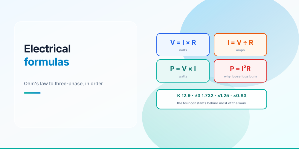
Most electrical cheat sheets are a wall of formulas with no indication of which one you need first, or where each stops applying. This one is organised by the order the formulas actually get used, and every entry says what its scope limit is - because on this subject the scope limits are where the mistakes live.
The three that catch the most people: the 90 °C column is a derating base, not an ampacity; the 3% voltage-drop figure is not enforceable code; and the 83% service allowance does not reach an ordinary subpanel feeder.
Ohm’s Law and Power
Know any two, and the other two follow
V = I × R          I = V ÷ R          R = V ÷ I          P = V × I
V = P ÷ I          I = P ÷ V          R = V² ÷ P         P = I² × R
V = √(P × R)       I = √(P ÷ R)       R = P ÷ I²         P = V² ÷ R
The one worth understanding rather than memorising is P = I²R. It says heat rises with the square of current, and linearly with resistance - which is exactly why a loose lug is dangerous. Half an ohm of contact resistance at 15 A dissipates 112.5 W inside a device box. Nothing about the circuit is overloaded; the connection is simply a small heater. It’s also why derating and terminal torque specs exist at all.
Conversions
DC:   I = P ÷ V                P = V × I
1φ:   I = P ÷ (V × PF)         P = V × I × PF
3φ:   I = P ÷ (√3 × V × PF)    P = √3 × V × I × PF

S (VA)   = V × I          (3φ: × √3)      ← what the conductor carries
P (W)    = S × PF                          ← what does work, and gets metered
Q (VAR)  = P × tan(arccos PF)              ← what capacitors cancel

kWh  = (W ÷ 1,000) × hours       cost = kWh × $/kWh
1 HP = 745.7 W (output)          1 W  = 3.412 BTU/h
Scope limits. Power factor never applies to DC, and must never be applied to a nameplate already given in VA - that double-counts it. On a motor, the nameplate horsepower is output, so input current is (HP × 745.7) ÷ (V × PF × efficiency) - and even that is only a sanity check, because NEC 430.6(A) requires motor conductors to be sized from the Table 430.248 / 430.250 full-load current instead.
Worked in detail in Watts to Amps and Amps to Watts.
→ Watts to Amps · Amps to Watts · kVA · Three-Phase Power · Power Factor · kWh Cost
The Order They Get Applied In
The formulas have an order, and it is always this one
This is the part no cheat sheet includes and every job needs. Steps 5 and 6 are two separate tests where the smaller answer wins, and steps 7 to 9 can each send you back to step 5 for a bigger conductor.
Conductor Sizing
Required ampacity = (continuous load × 1.25) + (non-continuous × 1.00)

Derated ampacity  = 90 °C column value × ambient factor × bundling factor
Usable ampacity   = min(derated value, 75 °C column value)      ← 110.14(C)

Ampacity-governed size = smallest conductor meeting required ampacity
Drop-governed size     = smallest conductor keeping drop within target
Final size             = the larger of the two
Scope limits. The 1.25 multiplier and the “80% rule” are the same rule (1 ÷ 1.25 = 0.80) - apply one, not both. 240.4(D) caps 14 AWG copper at 15 A, 12 AWG at 20 A and 10 AWG at 30 A no matter what Table 310.16 says, and it applies before anything else. Motors are routed out of these rules entirely by 240.4(G).
The 90 °C column is the single most misused number in the code. It is a starting point for derating only, because 110.14(C) limits the final answer to the terminal rating - normally 75 °C. That distinction is exactly what lets a 20 A breaker survive six bundled 12 AWG THHN conductors at 40 °C: 30 × 0.91 × 0.80 = 21.8 A, where starting from the 75 °C value of 25 A would have given 18.2 A and failed.
Full treatment in What Size Wire Do I Need and 12 Gauge Wire Amps; the tables themselves are on the NEC Tables reference.
→ Wire Size · Ampacity · Breaker Size
Voltage Drop
VD    = 2 × K × I × L ÷ CM              (3φ: replace 2 with 1.732)
drop% = VD ÷ circuit volts × 100
L_max = (limit% ÷ 100 × V × CM) ÷ (2 × K × I)

K  = 12.9 copper, 21.2 aluminum (ohm-cmil per foot)
L  = one-way run in feet; the 2 accounts for the return path
CM = circular mils - 12 AWG is 6,530
Scope limit, and it matters. The 3% branch / 5% total figures live in Informational Notes to 210.19(A) and 215.2(A). Informational notes are explanatory and not enforceable as code. Design to 3% anyway - it’s good practice and most engineers specify it - but don’t tell a customer or an inspector the NEC requires it, because it doesn’t.
Use the actual load current, not the breaker rating. A 20 A breaker feeding a 6 A load has almost no drop. And note that doubling the voltage doubles the reach: 12 AWG copper at a full 20 A holds 3% for about 46 ft on 120 V and 91 ft on 240 V.
Worked through in Voltage Drop Calculation.
Load Calculation and Service Sizing
Optional method - NEC 220.82
  general = (3 VA/ft² × area) + (1,500 VA × small-appliance circuits)
            + (1,500 VA × laundry) + Σ appliance nameplate VA
  demand  = 10,000 VA at 100% + (general − 10,000) × 0.40
  total   = demand + the larger of heating or cooling
  amps    = total ÷ 240

Existing load - NEC 220.87
  existing = highest 12-month recorded demand × 1.25
  total    = existing + new load (× 1.25 if continuous)

Dwelling service conductors - Table 310.12
  required ampacity = service rating × 0.83
Scope limits. 220.82 is available for a dwelling served by a single 120/240 V set of service conductors with an ampacity of 100 A or greater. Under 220.82(C), air conditioning and heat pumps count at 100% while central electric space heating counts at 65%, and only the larger of heating or cooling is counted (220.60).
The 83% allowance applies to a dwelling service, or the one feeder carrying an entire dwelling load - it does not reach an ordinary garage or shop subpanel feeder, which uses Table 310.16. That single misreading is the source of the widespread “4 AWG for a 100 A subpanel” answer, which is wrong for a normal subpanel; see What Size Wire for a 100 Amp Sub Panel.
220.87 is the most underused formula in the book. The utility’s recorded 12-month peak × 1.25 establishes the existing load on a real service, and it very often shows there is room for a new circuit without an upgrade - 30 days of recorded data is accepted where a year isn’t available.
Worked examples in Residential Load Calculation, What Size Electrical Service Do I Need and Do I Need a Panel Upgrade.
→ Load Calculator · Existing Load · Service Size · Service & Feeder Wire
Raceway and Box Fill
Conduit fill - Chapter 9, Tables 1, 4 and 5
  Σ conductor areas ≤ raceway internal area × fill limit
  fill limit: 53% for one conductor, 31% for two, 40% for three or more
  nipples 24 in or shorter: 60%, and exempt from bundling adjustment (Note 4)

Box fill - NEC 314.16
  volume = (each conductor × its Table 314.16(B) allowance)
         + (1 × largest allowance, if any internal clamps)
         + (2 × largest allowance, per device yoke)
         + (1 × largest EGC allowance, for all grounds together)
  allowances: 14 AWG 2.00 · 12 AWG 2.25 · 10 AWG 2.50 · 8 AWG 3.00 in³
Scope limits. Everything in the raceway counts toward fill, grounds included - but only current-carrying conductors count for derating. Those are different tallies and mixing them is the commonest conduit error. Note 7 to the Chapter 9 tables permits rounding up when the decimal is 0.8 or greater for conductors all of the same size, which is why Annex C sometimes reads one conductor higher than a strict calculation; for a mixed fill Note 7 doesn’t apply at all.
In box fill, the grouping rules are what people get wrong: clamps count once in total, all EGCs count once in total, each device yoke counts twice, and pigtails wholly inside the box count zero.
Worked in Conduit Fill Chart, How to Calculate Conduit Fill and Box Fill Calculation.
→ Conduit Fill · Box Fill
Grounding and Bonding
EGC  - Table 250.122, keyed to the OCPD rating
       upsized conductors: EGC × (installed CM ÷ required CM)   250.122(B)
GEC  - Table 250.66, keyed to the largest ungrounded service conductor,
       then capped by the electrode:
         rod, pipe or plate      → 6 AWG copper max     250.66(A)
         concrete-encased        → 4 AWG copper max     250.66(B)
         ground ring             → no larger than the ring   250.66(C)
         metal water pipe        → no cap
Scope limits. The EGC is keyed to the overcurrent device, not the conductor size, and 250.122(A) says it never has to be larger than the circuit conductors. Table 250.122 has no 30 A row - 25, 30, 35, 40, 45, 50 and 60 A all fall in the 60 A row, which is 10 AWG copper. Where one EGC serves several circuits, 250.122(C) sizes it to the largest OCPD.
Keep the two conductors distinct: the grounded conductor is the neutral and carries current in normal operation; the grounding conductor carries none until there’s a fault. Detail in Ground Wire Size Chart.
Pricing and Business
Loaded labor rate
  total cost  = (wage × paid hours × (1 + burden)) + annual overhead
  loaded cost = total cost ÷ (paid hours × billable %)
  bill rate   = loaded cost ÷ (1 − margin)

Job price
  break-even = (labor + material + fixtures) × (1 + overhead %)
  price      = break-even ÷ (1 − margin)        ← margin
  price      = break-even × (1 + markup)        ← markup, a different number
Scope limit - the one that costs real money. Margin is applied by dividing by (1 − margin); markup by multiplying. A 25% markup is only a 20% margin, and on a $2,979 break-even that’s $3,723 instead of $3,971 - $248 of profit given away on one job. A 50% markup is a 33% margin.
Worked in Electrician Hourly Rate and How to Estimate Electrical Jobs.
→ Labor Rate · Estimate
The Constants
The constants worth memorising
Common Mistakes
- Using the 90 °C ampacity as the answer. It’s a derating base; 110.14(C) caps the result at the terminal rating.
- Applying × 1.25 and ÷ 0.80 together. Same rule, twice.
- Claiming the NEC mandates 3% voltage drop. It’s an informational note, not a requirement.
- Using the 83% allowance on a subpanel feeder. Table 310.12 is for a service or a whole-dwelling feeder only.
- Using the breaker rating as I in the drop formula. Use the load.
- Skipping 240.4(D). It overrides the ampacity table for 14, 12 and 10 AWG.
- Counting grounds for derating. They count for fill, not for the adjustment factor.
- Sizing the EGC from the conductor. It’s keyed to the OCPD.
- Forgetting √3 on three-phase. Overstates current by 73%.
- Multiplying by (1 + margin). That’s markup, and it’s a smaller number than you think.
The Full Reference
Electrical Formula Reference - every formula above with its variables defined, its normal range, and a link straight to the calculator that solves it.
Alongside it, the NEC Tables reference carries Tables 310.16, 310.12, 240.6, 250.66, 250.122, 314.16 and the Chapter 9 conduit tables - all imported directly from the same data the calculators use, so the page and the tools can’t disagree. Terminology is in the Electrical Glossary, and all 28 tools are on the electrical calculator hub.
Sources & standards: NEC (NFPA 70) 2023 - 110.14(C), 210.19(A), 210.20(A), 215.2(A), 220.12, 220.52, 220.60, 220.82, 220.87, 240.4(D), 240.4(G), 240.6(A), Table 250.66, Table 250.122, Table 310.12, Table 310.16, 310.15(B)(1), 310.15(C)(1), 314.16, Chapter 9 Tables 1, 4, 5 and 8, 430.6(A). UL 943 for GFCI trip thresholds. Local amendments override the model code, and the AHJ has final say.
FAQ
What are the most important electrical formulas to know?
Ohm’s law and the power formula (V = IR, P = VI), the watts-to-amps conversion for your supply type, required ampacity as continuous load × 1.25, voltage drop as 2KIL ÷ CM, and the load calculation in NEC 220.82. Those five cover the large majority of residential and light commercial work.
What is the formula for voltage drop?
VD = 2 × K × I × L ÷ CM for single-phase, replacing the 2 with 1.732 for three-phase. K is 12.9 for copper and 21.2 for aluminum, I is the actual load current, L is the one-way run in feet and CM is the conductor area in circular mils. Divide the result by the circuit voltage for the percentage.
Is the 3% voltage drop limit required by the NEC?
No. The 3% branch-circuit and 5% total figures appear in Informational Notes to 210.19(A) and 215.2(A), and informational notes are explanatory rather than enforceable. Design to 3% because it’s sound practice, but it isn’t a code requirement - and an engineer’s specification or a local amendment can make it one.
Why can’t I just use the 90 °C ampacity column?
Because 110.14(C) limits a circuit to the temperature rating of its terminations, which are normally 75 °C. The 90 °C column exists as the starting point for derating: apply the ambient and bundling factors to the 90 °C value, then cap the result at the 75 °C figure. Starting from 75 °C throws away real capacity and can fail a bundled run that would otherwise pass.
What is the 80% rule in electrical work?
It’s NEC 210.20(A) stated backwards. The code requires the overcurrent device to be rated for 125% of a continuous load - anything running three hours or more - and 1 ÷ 1.25 = 0.80, so a continuous load may not exceed 80% of the breaker rating. Apply one form or the other, never both.
How do I convert HP to amps?
Amps = (HP × 745.7) ÷ (volts × power factor × efficiency), because nameplate horsepower is mechanical output rather than electrical input. Treat the result as a sanity check only: NEC 430.6(A) requires motor branch-circuit conductors to be sized from the Table 430.248 or 430.250 full-load current, not from the nameplate.
What’s the difference between markup and margin?
Markup is a percentage of cost; margin is a percentage of the selling price. A 25% markup gives a 20% margin, and a 50% markup gives 33%. To hit a target margin, divide the cost by (1 − margin) - multiplying by (1 + margin) is markup and leaves money on the table.