
Series vs Parallel Circuits: Why Every Building Is Wired in Parallel
- 06 Aug, 2026
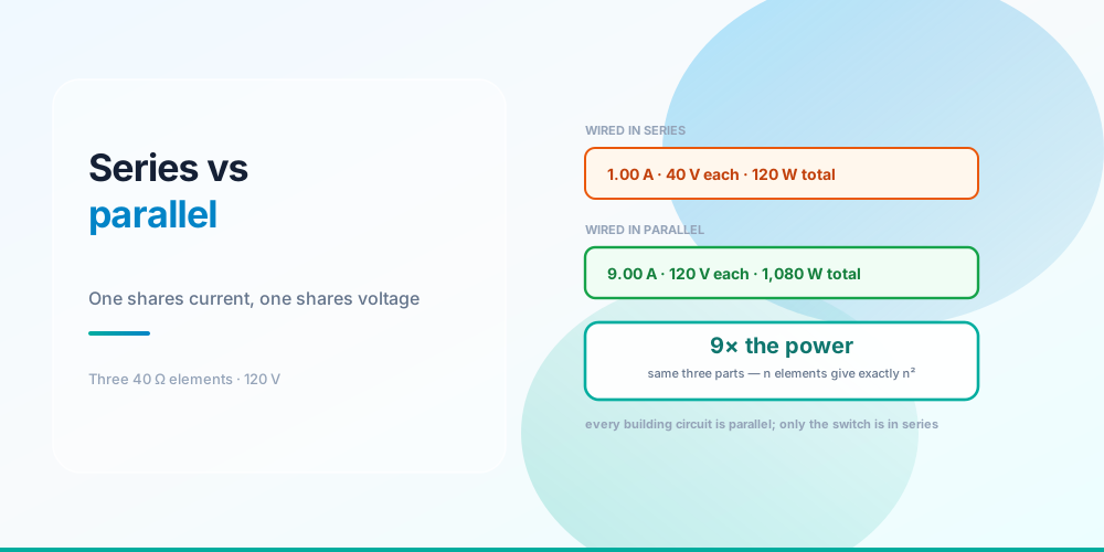
There is one sentence that separates the two, and everything else follows from it:
Series    - one path.  Current is shared, voltage divides.
Parallel  - many paths. Voltage is shared, current divides.
That’s it. If you can say which quantity is shared, you can work out the rest without memorising a single additional formula.
The reason it matters isn’t academic. Every branch circuit in every building is parallel, and understanding why explains a lot of things that otherwise look arbitrary - why plugging in a second appliance doesn’t dim the first, why a breaker goes in the hot leg, and why a loose wire nut gets hot enough to char a box.
The Same Parts, Wired Both Ways
One current or one voltage - that is the whole difference
| Series | Parallel | |
|---|---|---|
| Total resistance | 40 + 40 + 40 = 120 Ω | 1 ÷ (3 ÷ 40) = 13.33 Ω |
| Supply current | 1.00 A | 9.00 A |
| Across each element | 40 V | 120 V |
| Through each element | 1.00 A | 3.00 A |
| Each element dissipates | 40 W | 360 W |
| Total power | 120 W | 1,080 W |
Same three components, same supply. The parallel arrangement draws nine times the current and makes nine times the heat.
Look at what happens to total resistance, because this is the part that trips people up. In series, resistances add - the more you add the harder it gets for current to flow. In parallel, total resistance is always lower than the smallest branch, because every branch you add is another path. Three 40 Ω elements in parallel come to 13.33 Ω, less than any one of them alone.
That’s the counter-intuitive bit and it’s worth sitting with: adding load to a parallel circuit reduces the circuit’s resistance and increases the current. Which is precisely why a circuit can be overloaded by plugging in one more thing.
Why Buildings Are Wired in Parallel
Three reasons, all decisive.
Every device gets full voltage. A 120 V appliance needs 120 V. In series, three appliances would see 40 V each and none would work. In parallel every one sees the full supply, regardless of what else is connected.
Devices are independent. Unscrew one lamp in a parallel circuit and the others stay lit, because each has its own path. The old series Christmas light string is the classic counter-example - one bulb fails and the entire string goes dark, because breaking the single path stops all current.
Loads can be different sizes. In series, the current through a 1,500 W heater and a 9 W LED would have to be identical, which is impossible. In parallel each branch draws whatever its own resistance demands.
The cost of that convenience is that currents add at the panel. A 20 A branch circuit is a parallel bus, and the breaker is watching the sum of everything on it. That arithmetic is what How Many Outlets on a 20 Amp Circuit works through, and the load side of it is in What Size Breaker Do I Need.
The n² Rule
Adding elements in parallel multiplies power by n²
| Elements | Series total | Parallel total | Ratio |
|---|---|---|---|
| 2 | 180 W | 720 W | 4× |
| 3 | 120 W | 1,080 W | 9× |
| 4 | 90 W | 1,440 W | 16× |
| 5 | 72 W | 1,800 W | 25× |
The ratio is always n², and the reason is clean: series multiplies resistance by n while parallel divides it by n, so the two arrangements sit a factor of n² apart. Notice the series column falls as you add elements - more resistance, less current, less power. The parallel column climbs.
This is a useful sanity check in the field. If you rewire something and the current moves by a factor you didn’t expect, you probably changed the topology rather than the components.
Where Series Actually Shows Up
Buildings are parallel, but series is not gone - it’s doing specific jobs.
Anything that interrupts current is in series with the load. Switches, breakers, fuses, contactors, motor overloads. That’s the whole point of them: put a device in the single path and opening it stops everything downstream. It’s also why the switch goes in the ungrounded (hot) conductor - NEC 404.2(B) generally prohibits switching the grounded conductor, because a switch in the neutral would open the return path while leaving the load energised.
Control circuits are often series strings. Safety interlocks, limit switches and thermostats are wired so that any one of them opening stops the sequence. That’s a deliberate use of the series weakness.
Two devices are in series with each other when they share one current path - which is why an overload relay protects a motor even though the breaker upstream is sized far above the conductor. That split of duties is the subject of Motor Circuit Sizing.
And then there is the series circuit nobody designed.
The series circuit nobody draws on purpose
| Joint | Current | Volts at joint | Watts at joint | Volts at load |
|---|---|---|---|---|
| Perfect | 12.00 A | 0.00 V | 0 W | 120.00 V |
| 0.05 Ω | 11.94 A | 0.60 V | 7.1 W | 119.40 V |
| 0.10 Ω | 11.88 A | 1.19 V | 14.1 W | 118.81 V |
| 0.50 Ω | 11.43 A | 5.71 V | 65.3 W | 114.29 V |
| 1.00 Ω | 10.91 A | 10.91 V | 119.0 W | 109.09 V |
A loose termination is a resistor placed in series with the load, so the circuit becomes a voltage divider: the supply splits between the joint and the load in proportion to their resistances. Every volt the joint takes is a volt the load never sees, and every watt it takes is concentrated at one screw inside a plastic box.
This gives you the best field test there is. Measure voltage across a suspect connection while it carries load. A good termination shows essentially nothing; a bad one shows real volts. Testing resistance on a dead joint is far less reliable, because bad connections often read fine cold. The heat side of the same arithmetic is in Ohm’s Law Explained, and the failure signature is what an arc-fault device listens for - see GFCI vs AFCI and AFCI and GFCI Nuisance Tripping.
Kirchhoff, in Two Lines
The formal statement of everything above:
KCL - current into a junction = current out of it
KVL - voltages around any closed loop sum to zero
Kirchhoff’s current law is why branch currents add at the panel. Kirchhoff’s voltage law is why the drops around a series loop add up to the supply - 40 + 40 + 40 = 120 in the example above, exactly.
KVL is also the honest description of voltage drop. A conductor is a small resistance in series with the load, so it takes its share of the supply, and the load gets what’s left. That’s the whole concept, worked properly in Voltage Drop and collected with the rest of the algebra in the Electrical Formulas Cheat Sheet.
Conductors in Parallel Are a Code Topic
Running two conductors in parallel to carry one circuit’s current is legal but tightly controlled, because parallel branches share current only if they present equal impedance. NEC 310.10(G) permits it for sizes 1/0 and larger, and requires the parallel conductors in each phase to be the same length, same material, same size, same insulation and terminated the same way.
Miss any of those and the current splits unevenly - the lower-impedance conductor takes more than its share and can overheat while its partner loafs. The 1/0 floor exists because on smaller conductors the differences are proportionally too hard to control.
Common Mistakes
- Adding parallel resistances like series ones. Three 40 Ω in parallel is 13.33 Ω, not 120 Ω. Total parallel resistance is always below the smallest branch.
- Thinking more load means more resistance. In a parallel circuit, more load means less resistance and more current. That’s why a circuit overloads.
- Expecting voltage to divide between appliances. It divides in series only. In parallel every device sees the full supply.
- Switching the neutral. The switch belongs in the ungrounded conductor - 404.2(B). A switched neutral leaves the load live when it’s “off”.
- Assuming a bad joint just wastes energy. It also robs the load of voltage, and it puts all its heat in one spot.
- Paralleling small conductors. 310.10(G) starts at 1/0, and every parallel conductor must match in length, size, material and termination.
- Forgetting that series current is identical everywhere. If you measure different currents at two points in a series path, you have a fault, not a measurement.
- Treating the n² rule as a formula to memorise. It falls out of the resistance arithmetic; derive it rather than remember it.
Run the Numbers
Ohm’s Law Calculator - enter any two of volts, amps, ohms and watts and it returns the other two, which is all the arithmetic on this page.
For the load side of a parallel branch circuit use the Watts to Amps Calculator and the Receptacle & Circuit Calculator. For the series resistance of the conductors themselves, the Voltage Drop Calculator and the Conductor Resistance Calculator do the work, and Watts to Amps covers the conversion most often needed on site.
Sources & standards: series and parallel behaviour, Kirchhoff’s laws and the power relationships are physics rather than code. Code references are NEC (NFPA 70) 2023: 404.2(B) for switching the ungrounded conductor, and 310.10(G) for conductors in parallel. Worked figures use 40 Ω elements on a nominal 120 V supply and a 10 Ω load for the voltage-divider example; real terminations and appliances vary. A licensed electrician and the authority having jurisdiction have final say on anything installed.
FAQ
What is the difference between a series and a parallel circuit?
A series circuit has one path, so the same current flows through every component and the supply voltage divides between them. A parallel circuit has several paths, so every branch sees the full supply voltage and the branch currents add up. Naming which quantity is shared - current in series, voltage in parallel - gets you to every other answer without extra formulas.
Why is house wiring parallel instead of series?
Three reasons. Every device needs the full 120 V to work, and in series it would only get a fraction. Devices must be independent, so switching one off or having one fail can’t kill the rest. And loads of wildly different sizes have to coexist, which is impossible in series because the current would have to be identical through a 1,500 W heater and a 9 W LED.
How do you calculate total resistance in parallel?
Add the reciprocals and invert: 1 ÷ R_total = 1/R₁ + 1/R₂ + 1/R₃. For three 40 Ω elements that gives 1 ÷ (3/40) = 13.33 Ω. For n identical resistances there’s a shortcut - just divide one of them by n. The total is always lower than the smallest individual branch, which is the opposite of series behaviour.
Does adding more devices to a circuit increase or decrease resistance?
In a parallel circuit, adding devices decreases total resistance and increases total current, because each new device is another path for current to take. This surprises people, but it’s exactly why a circuit trips when you plug in one appliance too many. In a series circuit adding devices increases resistance and decreases current.
Why does one bad bulb kill an entire series string?
Because there’s only one path. Breaking it anywhere stops current everywhere, so every lamp goes out at once. In a parallel string each lamp has its own path, so a failed lamp only removes itself. Old Christmas light sets were series to save copper, which is why finding the dead bulb was such a chore.
What is the n squared rule for parallel circuits?
n identical elements draw exactly n² times as much power in parallel as they do in series. Series multiplies the total resistance by n while parallel divides it by n, so the two sit a factor of n² apart. Three 40 Ω elements on 120 V give 120 W in series and 1,080 W in parallel - nine times.
Is a loose connection a series or a parallel fault?
Series. A degrading termination adds resistance directly in the current path, so it forms a voltage divider with the load. A 0.5 Ω joint on a 10 Ω load at 120 V takes 5.71 V and dissipates about 65 watts at a single screw, while the load drops to 114 V. The best way to find one is to measure voltage across the connection while it’s carrying load.
Why is the switch in the hot wire and not the neutral?
Because a switch is in series with the load, and you want it to interrupt the energised conductor. Switching the neutral would stop the current but leave the load connected to the ungrounded conductor, so anyone working on a fixture that is “off” would still find voltage at it. NEC 404.2(B) generally prohibits switching the grounded conductor for exactly this reason.
Can I run two wires in parallel to carry more current?
Only at 1/0 and larger, per NEC 310.10(G), and only if the parallel conductors in each phase match in length, material, size, insulation type and termination method. Parallel branches share current in proportion to their impedance, so any mismatch makes one conductor carry more than its share and overheat. Below 1/0 the tolerances are too tight to control reliably, so the code doesn’t allow it.